Knife pouch structure

A tool holder and tool handle technology, which is applied in the direction of manufacturing tools, metal processing machinery parts, positioning devices, etc., can solve the problems of complex connector design, increased wear of tool holders, and limited rotation space of tool handles, etc., to reduce guiding The difficulty of deviation correction, the reduction of production management costs, and the effect of facilitating fixed storage of tools

Pending Publication Date: 2022-08-05
OKADA SEIKI DANYANG CO LTD
View PDF6 Cites 0 Cited by
  • Summary
  • Abstract
  • Description
  • Claims
  • Application Information

AI Technical Summary

Problems solved by technology

However, this solution has big problems in specific production applications
Firstly, the fixing bolts install the fixing device above the bearing groove through the fixing holes, and several screw holes are recessed at the bottom of the bearing groove to fix the fixing device in the bearing groove. However, since the bottom of the groove is used to recess the screw hole, resulting in limited rotation space of the tool handle, once a fault occurs, it will inevitably pose a threat to the safety of the tool handle, that is to say, the structure does not effectively utilize the characteristics of the tapered perforation for effective layout
Secondly, the plan does not consider the use of an integral injection molded tool holder structure. Therefore, when the tool holder is installed in the tool magazine, the thickness will be inconsistent. Will increase pocket wear
The most important thing is that in the structure of the tool holder, the installation position of the revolving pin and the roller is not considered, but the design of the complicated connecting parts is carried out, which is not suitable for the plastic or plastic-steel integral molding structure

Method used


Image

  • Knife pouch structure
  • Knife pouch structure
  • Knife pouch structure

Examples


no. 1 example

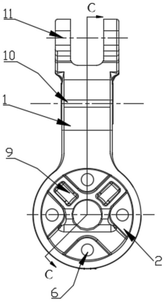
[0096] Knife cover structure, including knife cover 1 and base;

[0097] The inside of the knife sleeve 1 forms a cavity, and the cavity includes a through hole 17 and a through slot 3, and the through hole 17 communicates with the through slot 3,

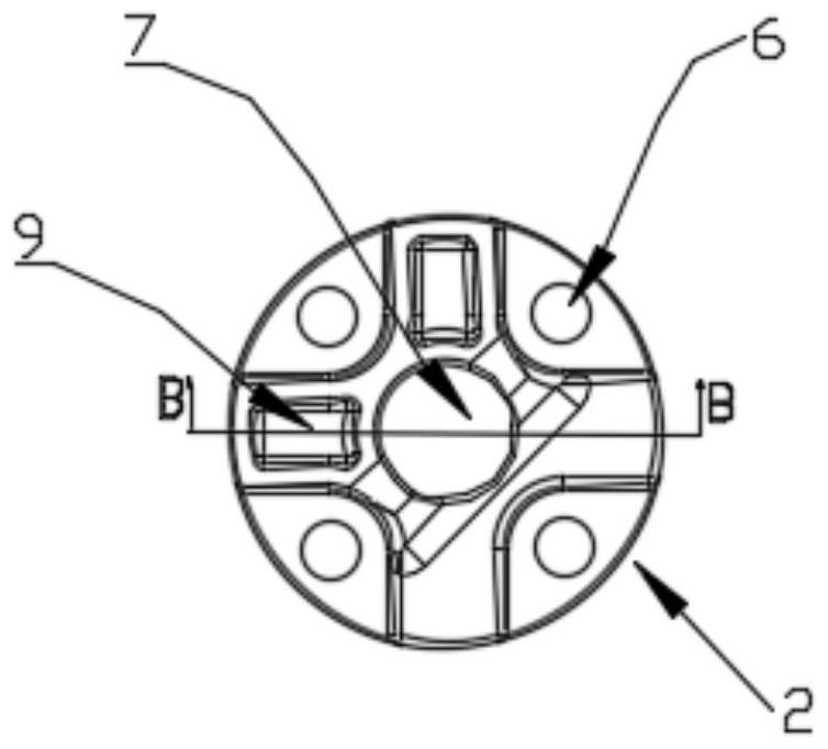
[0098] The base includes a fixed seat 2 and an elastic pressing member. A through hole 7 is formed inside the fixed seat 2. The peripheral wall of the fixed seat 2 is provided with an insertion hole 16 extending through the through hole 7. The hole 16 can be inserted into the elastic pressing member, and the base can be sleeved in the through slot 3 .

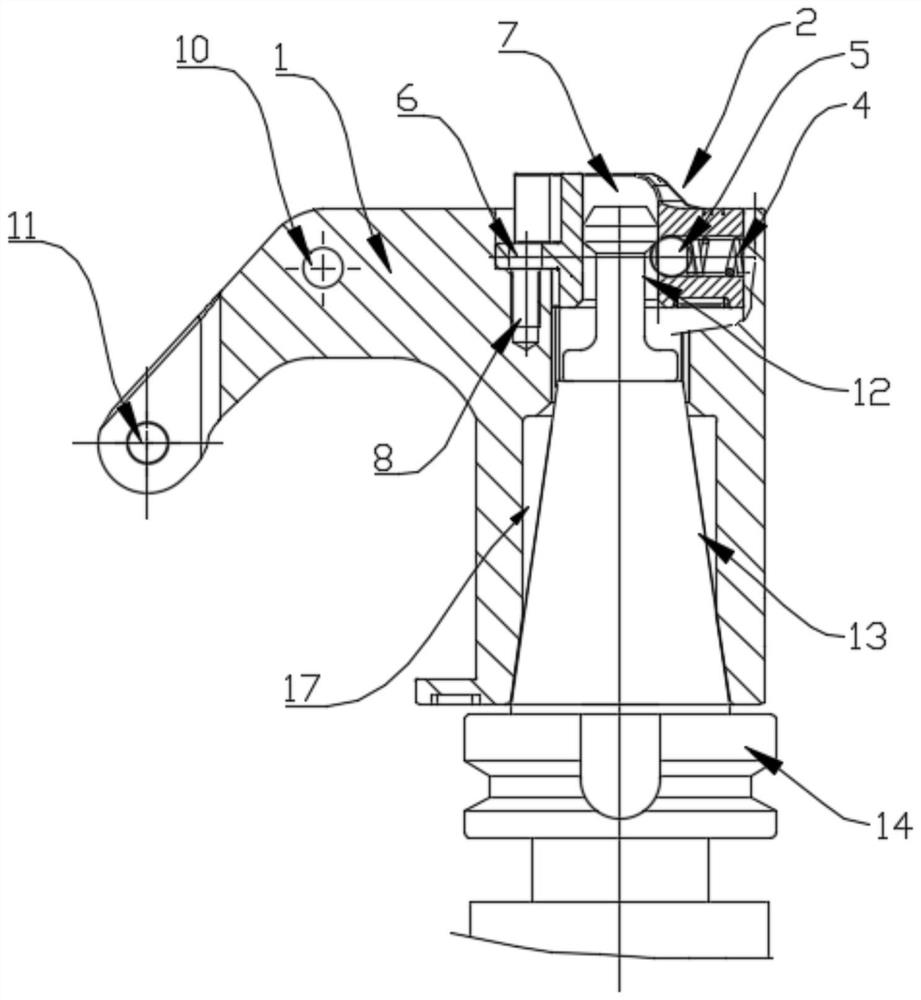
[0099] The cutter includes a cutter body 19 , a cutter base 14 , a cutter handle 13 and a pull stud 12 . The cutter body 19 , the cutter base 14 , the cutter handle 13 and the pull nail 12 are sequentially connected to form a whole. When the cutter needs to be fixed in the cutter holder 1 , the cutter The seat 14 is located outside the through hole 17, the knife handle 13 is insert...

no. 2 example

[0147] This embodiment can be applied in the same way as the first embodiment with respect to the bumps 18 and the recesses 20 and the width of the pressing surface 15 , and also includes another knife cover structure. Figure 8 , 9 , 10 and 5 and 6, including a knife sleeve 1 and a base; the inside of the knife sleeve 1 forms a cavity, and the cavity includes a through hole 17 and a through groove 3, and the through hole 17 communicates with the through groove 3, so The base includes a fixing seat 2 and an elastic pressing member. A through hole 7 is formed inside the fixing seat 2 . The fixing seat 2 is provided with an insertion hole 16 extending through the through hole 7 on the peripheral wall surrounding the through hole 7 . , the socket 16 can be used for the spring 4 and the bearing steel ball 5 to be placed in sequence.

[0148] Among them, such as Figure 8 As shown, the shape of the end of the through hole 17 away from the through-slot 3 is a shape adapted to the ...


PUM


Abstract

The invention discloses a knife pouch structure which comprises a knife pouch and a base. The tool pouch structure comprises the tool pouch and the base which are two independent parts, when a client wants to change and use tools of different forms, different bases are replaced, the whole tool pouch does not need to be disassembled, the operation efficiency is improved, and the production management cost is reduced. The end, away from the penetrating groove, of the penetrating hole is matched with the cutter handle in shape. In this way, the cutter handle can be prevented from shaking in the cutter sleeve, the cutter can be conveniently fixed and stored, the cutter handle can be conveniently positioned when being placed in the cutter sleeve, and the cutter can be conveniently guided and corrected in the process of being placed in the cutter sleeve. The part, except the end away from the penetrating groove, of the penetrating hole is in a shape not making contact with the cutter handle. In this way, machining cost is reduced, and entry and positioning of the cutter handle are facilitated. In the process of installing the base in the penetrating groove, the shape of the convex block is matched with that of the concave part, so that the concave part and the convex block can be in fit contact conveniently, the base can be positioned conveniently during installation, and the installation efficiency of the base is improved.

Description

technical field [0001] The invention relates to the field of tool pockets, in particular to a tool pocket structure. Background technique [0002] The comprehensive cutting center machine is a kind of machine that can perform various cutting tasks such as cutting, drilling, boring, surface scraping, etc. It places the machining tools in the tool pocket on the periphery of the tool magazine, and when it is to be replaced When the tool is used, the tool magazine is rotated through the process control, and the required tool and the tool holder are rotated to the bottom for a tool changing arm to exchange the tool with the tool located on the main shaft of the processing machine. The tool magazine is divided into vertical tool magazine or horizontal tool magazine according to the shape of the shell. According to the structure, it is usually divided into disc magazine, chain magazine, bucket hat magazine, etc. The most commonly used is the disc magazine. [0003] At present, the...

Claims


Application Information

Patent Timeline
IPC IPC(8): B23Q3/155B23Q3/157
CPCB23Q3/155B23Q3/15513B23Q3/157B23Q3/15713
Inventor 陈亮吴明刚曾燚刘涛
Owner OKADA SEIKI DANYANG CO LTD
Why Eureka
Try Eureka