Basement floor slab construction method based on stand column assembly type fixing

A construction method and basement floor technology, which can be used in infrastructure engineering, excavation, artificial islands, etc., can solve the problems of increased vertical calculation length, loss of restraint of columns, and weakened column bearing capacity, so as to achieve material selection and upgrade Stability and bearing capacity, the effect of improving practicality

Pending Publication Date: 2022-08-05
SHENZHEN GONGKAN GEOTECHN GRP
View PDF0 Cites 0 Cited by
  • Summary
  • Abstract
  • Description
  • Claims
  • Application Information

AI Technical Summary

Problems solved by technology

[0003] After the foundation pit is excavated to the bottom of the pit, the basement floor, basement outer wall, basement floor slabs of each floor, and support beams are constructed sequentially from bottom to top. After the support beams are removed, the columns lose the restraining effect of the original support beams, and the vertical length increase, the slenderness ratio increases, which weakens the bearing capacity of the column and affects the safety of the foundation pit

Method used


Image

  • Basement floor slab construction method based on stand column assembly type fixing
  • Basement floor slab construction method based on stand column assembly type fixing
  • Basement floor slab construction method based on stand column assembly type fixing

Examples


Embodiment 1

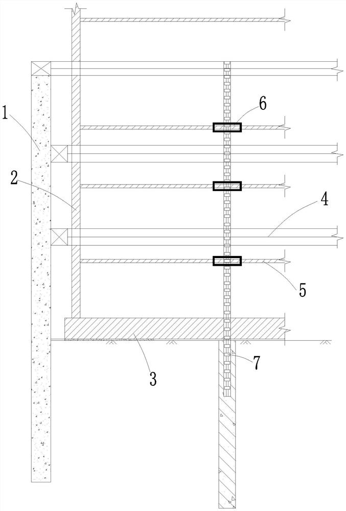
[0034] refer to Figure 1-4 As shown in the figure, the basement floor construction method based on the prefabricated and fixed column includes the following steps:

[0035] S1: Construct supporting pile 1, column 7, supporting beam 4 according to the requirements of the design drawings, and excavate the foundation pit to the bottom of the pit;

[0036] S2: Construct the basement floor 3, the basement exterior wall 2, and the bottom floor 5 in sequence. The bottom floor 5 reserves the hole space for the prefabricated fixture, and the floor 5 other than the reserved hole is poured with concrete, and the prefabricated fixture is installed in the reserved hole range. 6 and then remove the support beam 4 on the bottom floor;

[0037] S3: Continue the construction of the basement exterior wall 2, the sub-upper floor slab 5, reserve the hole space for the prefabricated fixing device for the sub-upper floor slab 5, and pour concrete for the floor slab 5 other than the reserved hole,...

Embodiment 2

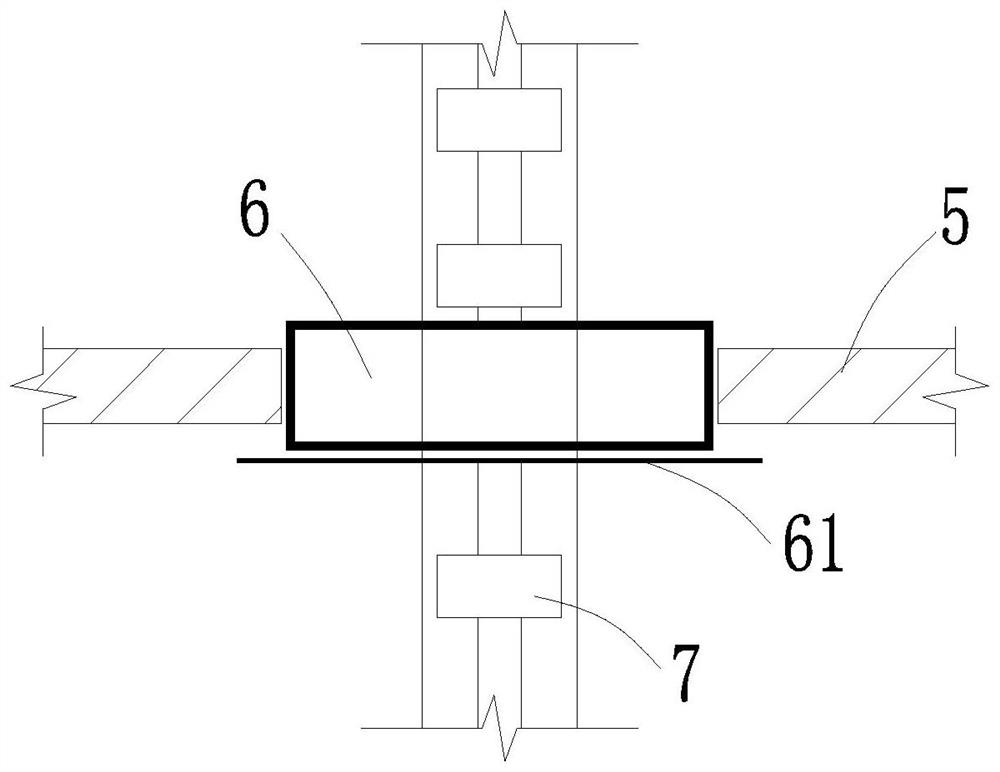
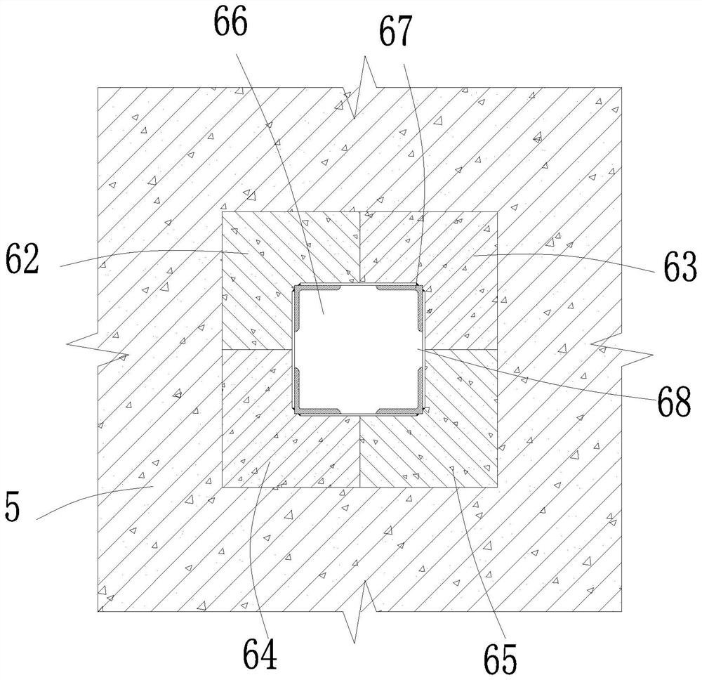
[0047] refer to Figure 1-2 , 5-6, the basement floor construction method based on the prefabricated and fixed column, specifically includes the following steps:

[0048] S1: Construct supporting pile 1, column 7, supporting beam 4 according to the requirements of the design drawings, and excavate the foundation pit to the bottom of the pit;

[0049] S2: Construct the basement floor 3, the basement exterior wall 2, and the bottom floor 5 in sequence. The bottom floor 5 reserves the hole space for the prefabricated fixture, and the floor 5 other than the reserved hole is poured with concrete, and the prefabricated fixture is installed in the reserved hole range. 6 and then remove the support beam 4 on the bottom floor;

[0050] S3: Continue the construction of the basement exterior wall 2, the sub-upper floor slab 5, reserve the hole space for the prefabricated fixing device for the sub-upper floor slab 5, and pour concrete for the floor slab 5 other than the reserved hole, an...


PUM


Abstract

The invention relates to the technical field of foundation pit supporting engineering, and discloses a basement floor slab construction method based on stand column assembly type fixing, which specifically comprises the following steps: S1, constructing a supporting pile, a stand column and a supporting beam according to the requirements of a design drawing, and excavating a foundation pit to a pit bottom; and S2, a basement bottom plate, a basement outer wall and the bottommost floor are sequentially constructed, the hole space of the fabricated fixing device is reserved in the bottommost floor, concrete is poured into the floor outside the reserved hole, and after the fabricated fixing device is installed in the range of the reserved hole, the supporting beam on the bottommost floor is dismantled. Temporary constraint is arranged at the position of the floor, constraint of a supporting beam before support dismounting is replaced, after the supporting beam is dismounted, the stability and bearing capacity of the stand column can be effectively guaranteed, the construction gap between the stand column and the floor is effectively filled, reliable constraint is provided, meanwhile, rectangular or circular stand column grooves can be prefabricated, and the construction efficiency is improved. The cross section forms of rectangular stand columns, circular stand columns and the like can be used, and therefore the practicability of the assembly type fixing device is improved.

Description

technical field [0001] The patent of the present invention relates to the technical field of foundation pit support engineering, in particular, to a basement floor construction method based on column assembly and fixation. Background technique [0002] At present, the inner support structure is widely used in the field of foundation pit support engineering. Usually, 1 to 3 inner supports need to be set up, and vertical columns are arranged at a certain distance directly below the support beams as vertical support members. [0003] After the foundation pit is excavated to the bottom of the pit, the basement floor, the basement exterior wall, the basement floor of each layer, and the support beams are removed in sequence from bottom to top. If it increases, the slenderness ratio increases, which weakens the bearing capacity of the column and affects the safety of the foundation pit. SUMMARY OF THE INVENTION [0004] The purpose of the present invention is to provide a basem...

Claims


Application Information

Patent Timeline
IPC IPC(8): E02D29/045E02D17/04E02D17/02E02D17/00E02D15/02
CPCE02D29/045E02D17/04E02D17/02E02D17/00E02D15/02Y02E10/20
Inventor 石洋海王贤能
Owner SHENZHEN GONGKAN GEOTECHN GRP
Why Eureka
Try Eureka