Driving loop of pneumatic cushion valve

A driving circuit and buffer valve technology, which is applied in the field of stamping machines, can solve the problems of large pressure fluctuations in the gas storage tank and reduce the internal heat generation of the buffer valve, etc.

Pending Publication Date: 2022-08-05
ZHEJIANG WANLI UNIV
View PDF0 Cites 0 Cited by
  • Summary
  • Abstract
  • Description
  • Claims
  • Application Information

AI Technical Summary

Problems solved by technology

[0004] In view of the above-mentioned shortcomings, the present invention proposes a method that does not need to expand the volume of the gas storage tank, and can also solve the problem of large pressure fluctuations in the gas storage tank when the stamping machine is started and in use, thereby reducing the internal heat generation of the buffer valve and ensuring The cushion valve is small in size, and can avoid the constant change of the state of the regulating valve at the same time, and can also make the cushion valve achieve a good cushioning effect. A driving circuit of a pneumatic cushion valve

Method used


Image

  • Driving loop of pneumatic cushion valve
  • Driving loop of pneumatic cushion valve
  • Driving loop of pneumatic cushion valve

Examples


Embodiment Construction

[0028] The embodiments of the present invention will be further described below with reference to the accompanying drawings.

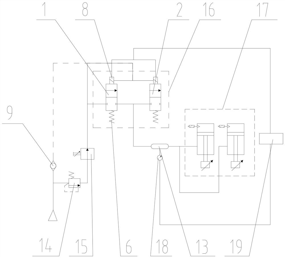
[0029] like figure 1 As shown, a driving circuit of a pneumatic buffer valve includes a punching cylinder 17 and an air storage tank 13. One end of the air storage tank 13 is connected to the punching cylinder 17 for buffering the air pressure change of the punching cylinder 17. The air storage tank The other end of 13 is connected with the regulating valve 15 and the pressure reducing valve 14 in series. The regulating valve 15 is arranged between the gas storage tank 13 and the pressure reducing valve 14, and a pneumatic Buffer valve 16, when the air storage tank 13 is pressurized, the pneumatic buffer valve 16 is used to exhaust and depressurize the air storage tank 13, and when the air storage tank 13 is depressurized, the pneumatic buffer valve 16 is used to The air storage tank 13 is supplemented and pressurized. The pneumatic buffer valve 16 is...


PUM


Abstract

The invention discloses a driving loop of a pneumatic cushion valve, which comprises a stamping air cylinder and an air storage tank, one end of the air storage tank is connected with the stamping air cylinder and is used for buffering the air pressure change of the stamping air cylinder, the other end of the air storage tank is connected with a regulating valve and a pressure reducing valve which are connected in series, and the pneumatic cushion valve is arranged between the air storage tank and the regulating valve. The pneumatic buffer valve is used for exhausting and depressurizing the air storage tank, and when the air storage tank depressurizes, the pneumatic buffer valve is used for supplementing air and pressurizing the air storage tank. According to the buffer valve, the size of the air storage tank does not need to be enlarged, the problem that the pressure fluctuation of the air storage tank is large when a punching machine is started and used can be solved, internal heat production of the buffer valve is reduced, it is guaranteed that the size of the buffer valve is small, and meanwhile continuous change of the state of the adjusting valve can be avoided; the driving loop of the pneumatic cushion valve can enable the cushion valve to achieve a good buffering effect.

Description

technical field [0001] The invention belongs to the field of punching machines, in particular to a driving circuit of a pneumatic buffer valve. Background technique [0002] During the use of the stamping machine, in order to ensure the stamping effect of the stamping machine, the stroke of the stamping machine will reach hundreds of times per minute. To reduce the stability of the gas flow of the buffer valve, a gas storage tank will be connected to the buffer valve, and the exhausted gas will be discharged into the gas storage tank, and the inhaled gas will also come from the gas storage tank, so there will be continuous pressure in the gas storage tank When the pressure fluctuation of the air storage tank is greater than 0.02MPA, it will cause friction and heat generation of the air storage tank, which will affect the machining accuracy of the stamping machine. [0003] In order to reduce the pressure fluctuation of the gas storage tank, the traditional method is to expa...

Claims


Application Information

Patent Timeline
Patent Type & Authority Applications(China)
IPC IPC(8): F15B11/06F15B11/16
CPCF15B11/06F15B11/16Y02P70/10
Inventor 庄忠柱王航张伟刘文严翔刘朋飞林立郭志文滕叶莹
Owner ZHEJIANG WANLI UNIV
Why Eureka
Try Eureka