
Tunnel deformation monitoring method based on distributed multipoint strain and displacement conversion network

A strain monitoring and displacement conversion technology, applied in neural learning methods, biological neural network models, measurement devices, etc., can solve problems such as monitoring blind spots, poor spatial continuity, and inconvenient engineering applications, and achieve the effect of improving spatial continuity.

Active Publication Date: 2022-08-05
青岛益群地下城开发有限公司 +2
View PDF14 Cites 0 Cited by
  • Summary
  • Abstract
  • Description
  • Claims
  • Application Information

AI Technical Summary

Problems solved by technology

Total-station robot is one of the commonly used technologies for structural deformation monitoring of subway tunnels, but there are still insurmountable problems in this technology
On the one hand, subway tunnels often have long routes, which makes it difficult for this technology to achieve full visibility in some areas of the tunnel, and the measurement results are limited by optical conditions; on the other hand, the number of tunnel monitoring sections set by this technology is usually limited and the number of measurement points is small , the spatial continuity is poor, and there are monitoring blind spots
Distributed optical fiber monitoring technology is a new type of monitoring technology produced in recent years. This technology has the characteristics of distributed, long-distance, real-time, high precision and long durability. It can realize the spatial continuous monitoring of tunnel structures. However, this technology The direct monitoring data is structural strain, which is not convenient for practical engineering application

Method used


Image

  • Tunnel deformation monitoring method based on distributed multipoint strain and displacement conversion network
  • Tunnel deformation monitoring method based on distributed multipoint strain and displacement conversion network
  • Tunnel deformation monitoring method based on distributed multipoint strain and displacement conversion network

Examples


specific Embodiment approach 1

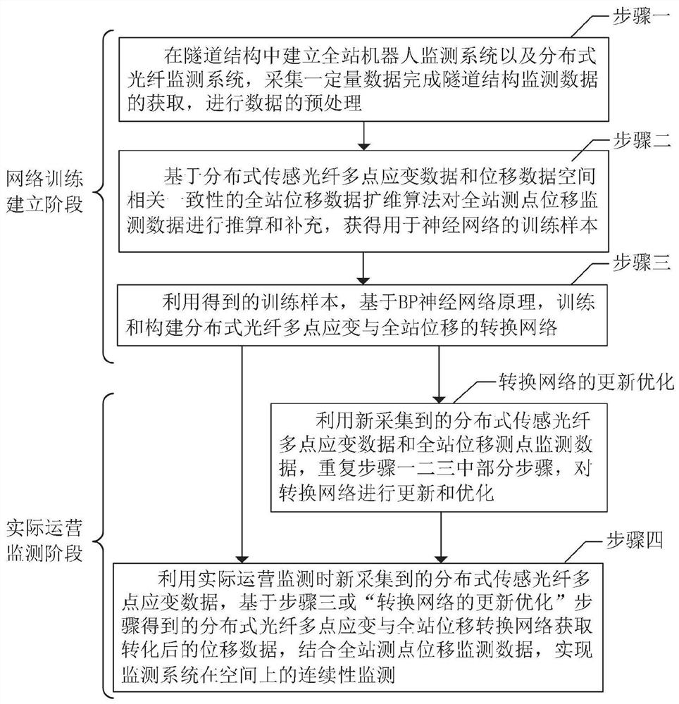
[0023] The tunnel deformation monitoring method based on distributed optical fiber multi-point strain and displacement conversion network, such as figure 1 As shown, the method includes the following steps:

[0024] Step 1: Establish a total-station robot displacement monitoring system and a distributed sensing optical fiber strain monitoring system respectively in the tunnel structure, and obtain the displacement monitoring data of the total-station measuring point and the distributed sensing optical fiber multi-point strain monitoring data I. The multi-point strain monitoring data I of the sensing fiber is subjected to mean preprocessing to obtain the multi-point strain monitoring data of the distributed sensing fiber II; the purpose of the mean preprocessing is to reduce the abnormal value of the multi-point strain monitoring data of the distributed sensing fiber. influences;

[0025] Step 2: Use the spatial correlation consistency between the distributed sensing optical f...

specific Embodiment approach 2

[0029] This embodiment is a further limitation of the specific embodiment 1. The described tunnel deformation monitoring method based on the distributed optical fiber multi-point strain and displacement conversion network, when acquiring the newly collected displacement monitoring data and distribution of the whole station measuring points during the operation monitoring based on the multi-point strain monitoring data of the multi-point sensing optical fiber, repeat steps 1, 2 and 3 to establish a new training sample set II, based on the set of training sample set I and training sample set II The displacement transformation network is updated and optimized.

specific Embodiment approach 3

[0030] This embodiment further describes the tunnel deformation monitoring method based on the distributed optical fiber multi-point strain and total station displacement conversion network described in the specific embodiment 1. The step 1 specifically includes the following steps:

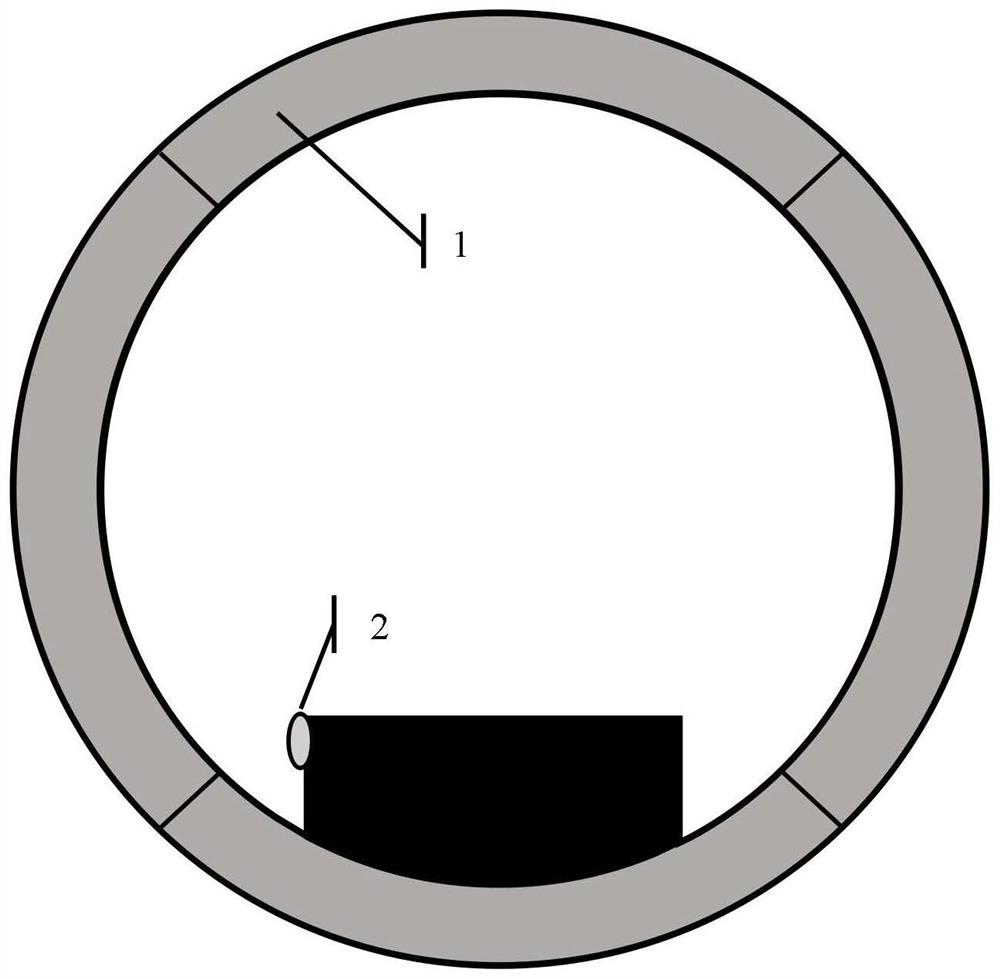
[0031] Step 11: Determine the key sections along the line, set up all-station measuring points, establish a total-station robot displacement monitoring system, and collect and obtain the displacement monitoring data of the total-station measuring points for several monitoring days;

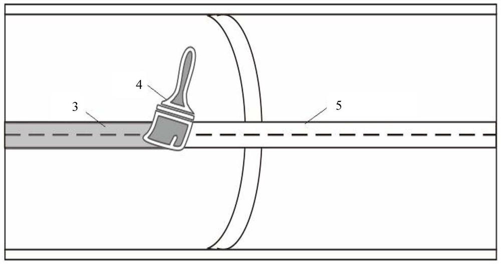
[0032] Step 1 and 2: Determine the installation position of the optical fiber, complete the grinding and dust removal, and coat the primer, arrange the distributed sensing optical fiber along the line, establish a distributed sensing optical fiber strain monitoring system, and collect the multi-point strain of the distributed sensing optical fiber for several monitoring days. Monitoring data I;

[0033]Step 1 and 3: ...


PUM


Abstract

The invention discloses a tunnel deformation monitoring method based on a distributed multipoint strain and displacement conversion network, belongs to the field of tunnel structure deformation monitoring, and provides a total station measuring point displacement monitoring data supplementary dimension expansion algorithm by utilizing the spatial correlation consistency of multipoint strain monitoring data of distributed sensing optical fibers and total station measuring point displacement monitoring data. Constructing a distributed optical fiber multi-point strain and total station displacement conversion network by using a BP neural network principle according to the distributed optical fiber multi-point strain data and the total station measuring point displacement data after supplementary dimension expansion; newly collected distributed sensing optical fiber multipoint strain data are used as input data, a return value of the conversion network is a displacement value corresponding to the distributed sensing optical fiber multipoint strain data, and continuous monitoring of the monitoring system in space is achieved in combination with displacement data output by the conversion network and total station measuring point displacement monitoring data. The whole-station robot and the distributed optical fiber monitoring technology can be organically combined, a better tunnel monitoring effect is achieved, and the method is good in effectiveness.

Description

technical field [0001] The invention belongs to the field of tunnel structure deformation monitoring, in particular to a tunnel deformation monitoring method based on a distributed optical fiber multi-point strain and displacement conversion network. Background technique [0002] Automatic deformation monitoring technology can provide an effective means to ensure the safety of subway tunnel structure operation. The total station robot is one of the commonly used technologies for monitoring the deformation of subway tunnel structures. However, this technology still has insurmountable problems. On the one hand, subway tunnels often have long routes, which makes it difficult for this technology to achieve visibility in some areas of the tunnel, and the measurement results are limited by optical conditions; on the other hand, the number of tunnel monitoring sections set by this technology is usually limited, and there are few measurement points. , the spatial continuity is poor...

Claims


Application Information

Patent Timeline
Patent Type & Authority Applications(China)
IPC IPC(8): G01B11/16G01B11/02G06N3/08
CPCG01B11/165G01B11/02G06N3/084
Inventor 潘同斌刘国文邱丙水魏绍军闫宇蕾刘洋
Owner 青岛益群地下城开发有限公司
Learn More