[0018] Below according to accompanying drawing and embodiment, the present invention is described in further detail:
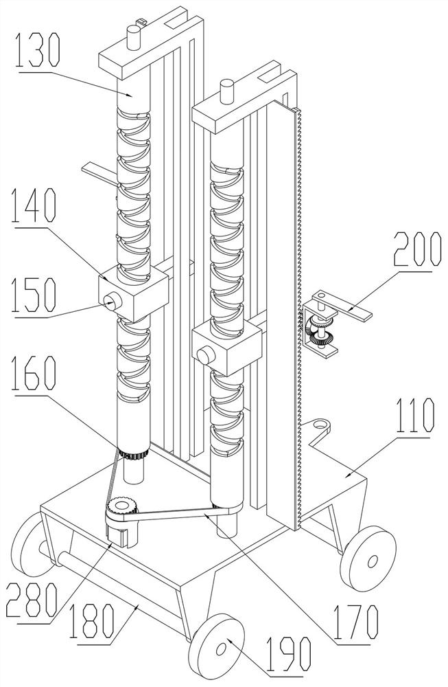
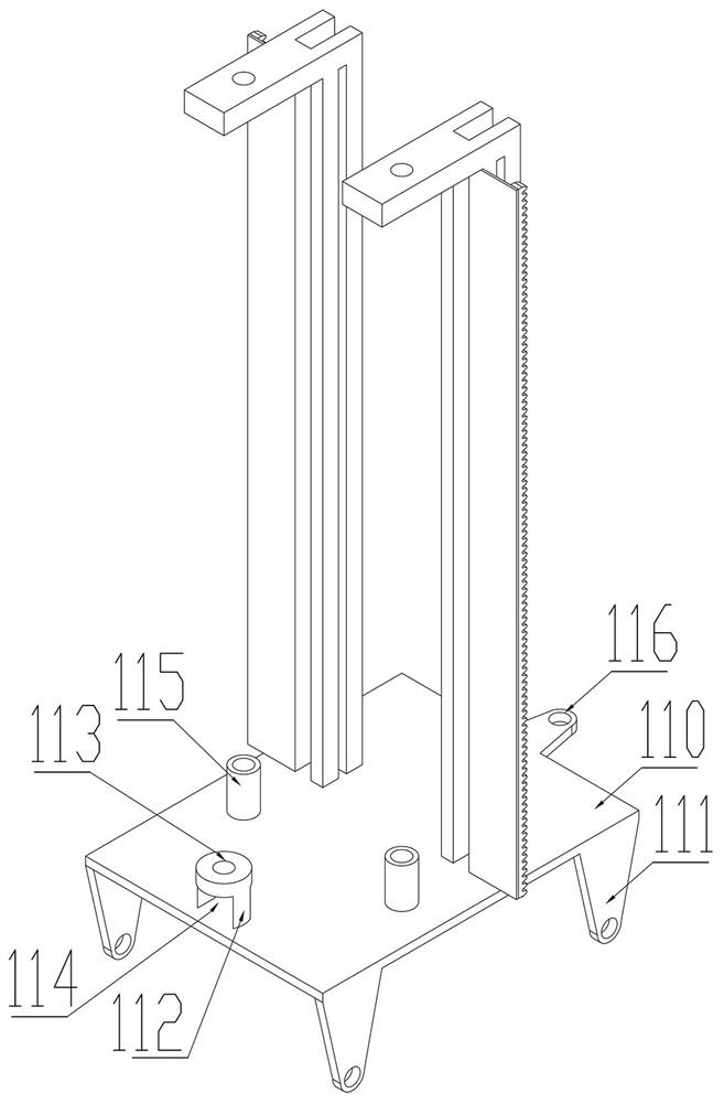
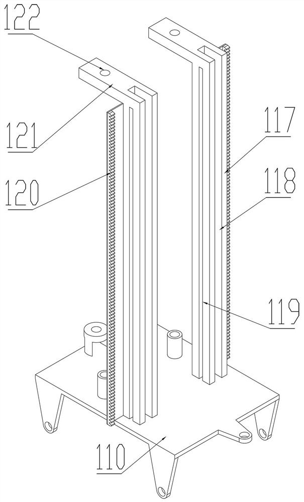
[0019] A corn spraying device and operation method, comprising a trolley 110, a rack 120, a screw shaft 130, a moving block 140, a diamond-shaped slider 150, and a swinging device 200. The swinging device 200 includes an arcuate seat 210 and a half-bevel gear 220. The lower part of the trolley 110 is evenly distributed with four bearing seats 111 , the middle of the left side of the trolley 110 has a shaft seat 112 , the middle of the shaft seat 112 has a shaft seat hole 113 , the lower part of the shaft seat 112 has a shaft seat groove 114 , and the right side of the shaft seat 112 has a shaft seat 114 . The front and rear symmetrical two bushings 115, each bushing 115 has a column 117 on the right side, each column 117 has a longitudinal slot 118 in the front and rear directions, each column 117 has a horizontal slot 119 in the left and right directions, and each column 117 has a The rack 120, the upper part of each column 117 has a transverse plate 121, the front part of each transverse plate 121 has a transverse plate hole 122, the cylindrical surface of the helical shaft 130 has a right helical groove 131 and a left helical groove 132, and the right helical groove 131 and the left helical groove 131. The grooves 132 are symmetrically arranged, and the two sides of the right helical groove 131 and the left helical groove 132 are connected by the transition groove 133. The slider 143, the right side of the vertical slider 143 has a horizontal slider 144, the outer side of the diamond slider 150 has a diamond slider shaft 151, a motor 280 is arranged in the middle of the shaft seat groove 114, the lower part of the motor 280 is fixedly connected to the upper part of the trolley 110, and the motor 280 outputs The shaft is rotated to connect the shaft seat hole 113, the upper part of the output shaft of the motor 280 is fixedly connected to the synchronizing wheel 160, a screw shaft 130 is arranged in each shaft sleeve 115, the lower part of each screw shaft 130 passes through a synchronizing wheel 160, and the lower part of each screw shaft 130 A synchronizing wheel 160 is fixedly connected, the lower part of each helical shaft 130 is rotatably connected to the shaft sleeve 115, each helical shaft 130 rotates in the shaft sleeve 115, the three synchronizing pulleys 160 are rotatably connected by a synchronous belt 170, and each helical shaft 130 is arranged outside A moving block 140, each central hole 141 is slidably connected to the screw shaft 130, each vertical slider 143 is slidably connected to the same side longitudinal groove 118, each transverse slider 144 is slidably connected to the same side transverse groove 119, and each diamond-shaped slider 150 The right helical groove 131 and the left helical groove 132 on the same side are slidably connected, and each diamond-shaped slider shaft 151 is rotatably connected to the slider hole 142 on the same side.
[0020] The arcuate seat 210 has an arcuate seat hole 211 in the middle, the upper and lower sides of the arcuate seat 210 have coaxial swing shaft holes 212, one side of the half bevel gear 220 has a smooth surface 221, and the middle of the half bevel gear 220 has a half bevel gear shaft 222 , the half bevel gear shaft 222 passes through the arcuate seat hole 211 and the gear 260 from the inside to the outside, the half bevel gear shaft 222 rotates to connect the arcuate seat hole 211, the half bevel gear 220 rotates in the arcuate seat hole 211, and the outer side of the half bevel gear shaft 222 The gear 260 is fixedly connected, and the swing seat shaft 230 passes through the nozzle seat 270, the swing shaft hole 212, the No. 1 bevel gear 240 and the No. 2 bevel gear 250 in sequence from top to bottom. The swing seat shaft 230 is fixedly connected to the nozzle seat 270, and the swing seat shaft 230 is rotatably connected to the swing shaft hole 212, the swing seat shaft 230 rotates in the swing shaft hole 212, and the swing seat shaft 230 is fixedly connected to the first bevel gear 240 and the second bevel gear 250, and the first bevel gear 240 and the second bevel gear 250 At the same time, it meshes with the half-bevel gear 220, the lower part of the outer side of the arcuate seat 210 is fixedly connected to the outer side of the transverse slider 144, and the rack 120 and the gear 260 mesh with each other.
[0021] When using the present invention, the liquid medicine spray head is fixed on the upper part of the spray head seat 270, and the pulling device pulls the present invention through the pulling hole 116. In the initial state, the two moving blocks 140 are respectively at the lower part of the two screw shafts 130, and each diamond-shaped slider 150 is at the bottom of the two screw shafts 130. At the beginning of the right helical groove 131, each swinging device 200 is at the lower part of the helical shaft 130, starts the motor 280, the rotation of the gear 260 drives the synchronous wheel 160 fixedly connected to it to rotate, and the rotation of the synchronous wheel 160 drives the other two synchronous wheels through the synchronous belt 170. The wheel 160 rotates, and the two synchronizing wheels 160 drive the respective screw shafts 130 to rotate. When the screw shaft 130 rotates, the right helical groove 131 drives the diamond-shaped slider 150 to move upward, and the moving block 140 follows the diamond-shaped slider 150 along the longitudinal grooves 118 and 118 . The horizontal slot 119 slides up, the moving block 140 drives the swing device 200 to move up, when the swing device 200 moves up, the gear 260 rolls along the rack 120, the gear 260 drives the half bevel gear 220 to rotate, the half bevel gear 220 and the second gear When the bevel gear 250 meshes, the half bevel gear 220 drives the No. 2 bevel gear 250 to rotate. At this time, the smooth surface 221 is opposite to the No. 1 bevel gear 240, the No. 1 bevel gear 240 does not rotate, and the half bevel gear 220 and the No. 1 bevel gear 240 mesh When the semi-bevel gear 220 drives the No. 1 bevel gear 240 to rotate in the opposite direction, the smooth surface 221 is opposite to the No. 2 bevel gear 250, the No. 2 bevel gear 250 does not rotate, and the No. 1 bevel gear 240 and the No. 2 bevel gear 250 are in The half bevel gear 220 drives the lower gap to rotate, the swing seat shaft 230 rotates back and forth under the action of the No. 1 bevel gear 240 and the No. 2 bevel gear 250, the swing seat shaft 230 drives the nozzle holder 270 to swing back and forth, and the nozzle holder 270 drives the swing device 200 back and forth Swing, when the diamond-shaped slider 150 and the moving block 140 move to the upper part, the diamond-shaped slider 150 transitions from the right helical groove 131 to the left helical groove 132, the diamond-shaped slider 150 slides down under the action of the left helical groove 132, and the motor 280 does not Stop the rotation, the diamond-shaped slider 150 drives the moving block 140 to move up and down, and the moving block 140 drives the swing device 200 to move up and down. During the up and down movement of the swing device 200, the nozzle seat 270 drives the liquid spray nozzle to swing, and the corn is completely sprayed from the root to the head. , the above components cooperate smoothly, the force is balanced, the balance is good, the vibration is effectively prevented, and the jamming is prevented, the swing of the swing device 200 is realized, and the swing speed of the swing device 200 is stable, so that the spraying is more uniform. The effect of removing diseases and insect pests is good, and at the same time, it avoids the problem that pesticides are sprayed from the upper part of the corn and the effect is not uniform, and at the same time, it avoids the residue of pesticides on the upper part of the corn, which is harmful to human health.
[0022]The invention can spray the pesticides in all directions and evenly, so that the corn can be covered by the pesticides from the top to the roots, and the effect of removing diseases and insect pests is good, avoiding the problem that the pesticides are sprayed from the upper part of the corn and the drug effect is not uniform, and at the same time avoiding the pesticides on the upper part of the corn. It causes residues and endangers human health. When spraying, the swinging device 200 moves back and forth along the corn from top to bottom and swings left and right, and the entire corn is completely covered. The screw shaft 130 cooperates with the moving block 140 and the diamond-shaped slider 150 to realize the cyclic movement of the swing device 200 up and down. 150 cyclically moves up and down in the closed groove, and the moving speed is uniform to ensure uniform dose during spraying. The moving block 140 slides and connects the screw shaft 130 and the trolley 110 at the same time. The stable contact between the diamond-shaped slider 150 and the right helical groove 131 and the left helical groove 132 ensures the stable sliding of the diamond-shaped slider 150. When the swing device 200 moves up and down, the rack 120 and the half-bevel gear 220 mesh with each other to realize the swing device 200. When swinging left and right, the rack 120 and the gear 260 mesh with each other, which not only realizes the swinging of the swinging device 200, but also stabilizes the swinging speed of the swinging device 200, making the spraying more uniform. The effect of removing pests and diseases is good, and at the same time, it avoids the problem that pesticides are sprayed from the upper part of the corn and the effect is uneven, and at the same time, it avoids the residue of pesticides on the upper part of the corn, which is harmful to human health.
[0023] A corn spraying device and operation method, characterized in that: comprising the following steps: the first step, the spray nozzle of the liquid medicine is fixed on the upper part of the nozzle seat 270, the pulling device pulls the corn spraying device through the pulling hole 116, and the second step, starting the motor 280. During the up and down movement and the left and right swing of the swinging device 200, the corn is completely sprayed by the spray nozzle from the root to the head.
[0024] When using the present invention, the liquid medicine nozzle is fixed on the upper part of the nozzle seat, and the traction device pulls the present invention through the traction hole. In the initial state, the two moving blocks are respectively at the lower part of the two helical shafts, and each diamond-shaped slider starts from the right helical groove. Each swinging device is located at the lower part of the screw shaft, the motor is started, and the rotation of the gear drives the rotation of the synchronous wheel that is fixedly connected to it. Rotation, when the screw shaft rotates, the right helical groove drives the diamond-shaped slider to move upward, the moving block slides up along the longitudinal groove and the horizontal groove with the diamond-shaped slider, and the moving block drives the swing device to move up. When the swing device moves up, The gear rolls along the rack, and the gear drives the half bevel gear to rotate. When the half bevel gear meshes with the No. 2 bevel gear, the half bevel gear drives the No. 2 bevel gear to rotate. At this time, the smooth surface is opposite to the No. 1 bevel gear, and the No. 1 bevel gear will not. Rotation, when the half bevel gear meshes with the No. 1 bevel gear, the half bevel gear drives the No. 1 bevel gear to rotate in the opposite direction. At this time, the smooth surface is opposite to the No. 2 bevel gear, and the No. 2 bevel gear will not rotate. The No. 1 bevel gear rotates intermittently under the driving of the half-bevel gear, the swing seat shaft rotates back and forth under the action of the No. 1 bevel gear and the No. 2 bevel gear, the swing seat shaft drives the nozzle seat to swing back and forth, and the nozzle seat drives the swing device to swing back and forth. After the slider and the moving block move to the upper part, the diamond-shaped slider transitions from the right helical groove to the left helical groove, the diamond-shaped slider slides down under the action of the left helical groove, the motor keeps rotating, and the diamond-shaped slider drives the moving block to move up and down, The moving block drives the swing device to move up and down. During the up and down movement of the swing device, the nozzle seat drives the potion nozzle to swing, and the corn is completely sprayed from the root to the head.