Ancient building underground drainage pipe ditch detection system and method

A detection system and drainage pipe technology, applied in closed-circuit television systems, manufacturing tools, manipulators, etc., can solve the problems of no targeted robots, etc., and achieve the effects of easy promotion and use, high-precision collection, and simple structure

Pending Publication Date: 2022-08-09
中兵勘察设计研究院有限公司
View PDF0 Cites 0 Cited by
  • Summary
  • Abstract
  • Description
  • Claims
  • Application Information

AI Technical Summary

Problems solved by technology

However, for the operation and maintenance of ancient buildings and the protection of cultural relics, it is necessary to detect and collect comprehensive detailed data on the underground drainage pipes of ancient buildings. At present, there is no targeted robot

Method used


Image

  • Ancient building underground drainage pipe ditch detection system and method
  • Ancient building underground drainage pipe ditch detection system and method
  • Ancient building underground drainage pipe ditch detection system and method

Examples


Embodiment 1

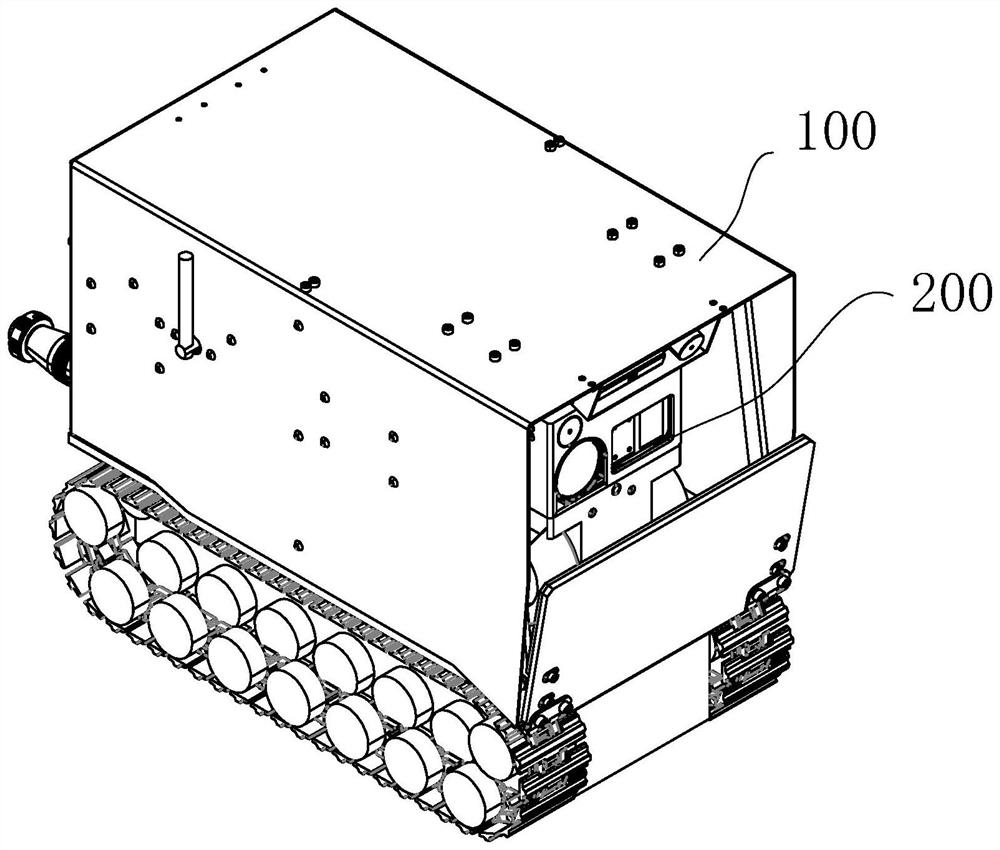
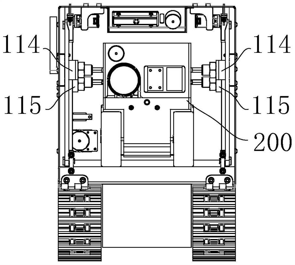
[0074] refer to figure 1 and figure 2 , the first aspect of the present application discloses a detection system for underground drainage pipe trenches of ancient buildings, including a master control center, and a main robot system 100, a reconnaissance and obstacle removal robot system 300, and a detection and perception robot system 200 connected to its signals; the main robot The system 100 is used to carry a reconnaissance obstacle removal robot system 300 and a detection and perception robot system 200; the reconnaissance obstacle removal robot system 300 is used for reconnaissance lighting, reconnaissance photography and obstacle removal; the detection and perception robot system 200 is used to collect three-dimensional information of the area to be detected and Rescue; the general control center is used to control the operation of the main robot system 100, the reconnaissance and obstacle removal robot system 300, and the detection and perception robot system 200, to ...

Embodiment 2

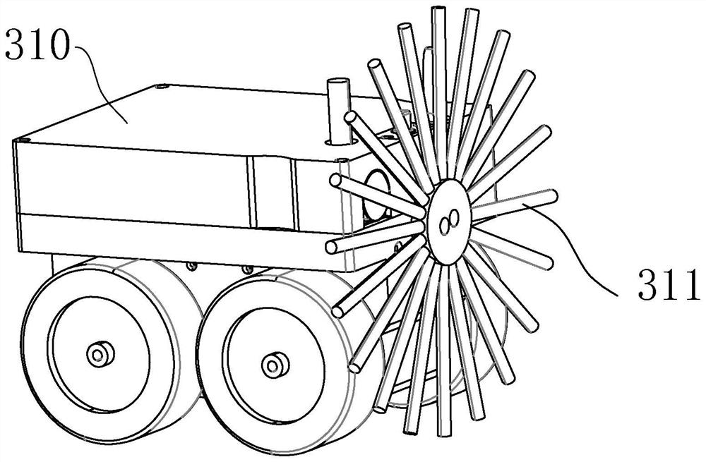
[0115] On the basis of the first embodiment, the reconnaissance obstacle removal robot system is further provided with a dozer device, and the dozer device includes a first rotary motor, a second rotary motor, a first cantilever, a second cantilever and a bucket, wherein the first cantilever is One end of the cantilever is fixed at the power output end of the first rotating motor, and the other end is fixedly connected with one side of the bucket; one end of the second cantilever is fixed at the power output end of the second rotating motor, and the other end is connected with the other end of the bucket. side fixed connection; in the initial state, the bucket is buckled upside down on the top of the first sub-robot; in the working state, the first cantilever and the second cantilever drive the bucket respectively under the driving of the first rotating motor and the second rotating motor Rotate outward to the front of the obstacle removal device, and the first cantilever, the ...

Embodiment 3

[0118] On the basis of the first embodiment, the troubleshooting device is improved.

[0119] The reconnaissance obstacle-removing robot system is also provided with a dozer device, which includes a first rotary motor, a second rotary motor, a first cantilever, a second cantilever and a bucket, wherein one end of the first cantilever is fixed on the first rotary The other end of the power output end of the motor is fixedly connected to one side of the bucket; one end of the second cantilever is fixedly connected to the power output end of the second rotating motor, and the other end is fixedly connected to the other side of the bucket.

[0120] A bearing member is arranged between the first cantilever and the second cantilever for installing an obstacle removal device; the obstacle removal device is arranged behind the bucket and does not interfere with the bucket.

[0121] The troubleshooting device is controlled by the installed first motor to start or stop, and the installe...


PUM


Abstract

The invention relates to the technical field of pipe ditch detection, in particular to an ancient building underground drainage pipe ditch detection system and method, and aims to obtain comprehensive patrol information of an ancient building underground drainage pipe ditch. The system comprises a master control center, a main robot system, a reconnaissance and obstacle removal robot system and a detection and sensing robot system. The reconnaissance and obstacle removal robot system is used for reconnaissance illumination, reconnaissance The main robot system can carry the reconnaissance and obstacle removal robot system and the detection and sensing robot system to collect information of a first area, and can release the reconnaissance and obstacle removal robot system to remove obstacles in a second area under the control of the master control center; the detection and sensing robot system operates to be in butt joint with the reconnaissance and obstacle removal robot system based on control of the master control center, and rescue is conducted on the reconnaissance and obstacle removal robot system through the detection and sensing robot system under the pulling force of the main robot system. According to the invention, automatic patrol and comprehensive patrol of different types of pipe ditches can be realized.

Description

technical field [0001] The present application relates to the technical field of pipe trench detection, and in particular, to a detection system and method for underground drainage pipe trenches of ancient buildings. Background technique [0002] The underground drains of ancient buildings are very different from those of modern buildings. The underground drainage pipes of modern buildings are often reinforced concrete prefabricated round pipes or square pipes, reinforced concrete cast-in-place round pipes or square pipes, brick masonry square pipes or round pipes, PVC pipes, etc. The branch pipes are usually 0.5m ~1.0m, the secondary trunk is usually 1.0m~2.0m, the main trunk is usually 2.0~3.0m, and the comprehensive pipe gallery is larger; then the underground drainage pipes of ancient buildings are often brick, stone, rammed, ceramic Pipes, etc., the size is small, the branch is usually 0.2m ~ 0.4m, the secondary trunk is usually 0.4m ~ 0.7m, and the trunk is usually 0....

Claims


Application Information

Patent Timeline
Patent Type & Authority Applications(China)
IPC IPC(8): B25J11/00B25J19/00B25J19/02H04N7/18
CPCB25J11/00B25J19/00B25J19/02H04N7/18
Inventor 赵术强刘卫华沈健曹璞琳刘音陈鹏飞
Owner 中兵勘察设计研究院有限公司
Why Eureka
Try Eureka