A self-charging tape machine omnidirectional inspection robot
A technology of inspection robot and tape machine, which is applied in the field of all-round inspection robot of self-charging tape machine, can solve problems such as blind spots, small space, sound, temperature and other information cannot be collected, and achieve the effect of reducing difficulty
- Summary
- Abstract
- Description
- Claims
- Application Information
AI Technical Summary
Problems solved by technology
Method used
Image
Examples
Embodiment 1
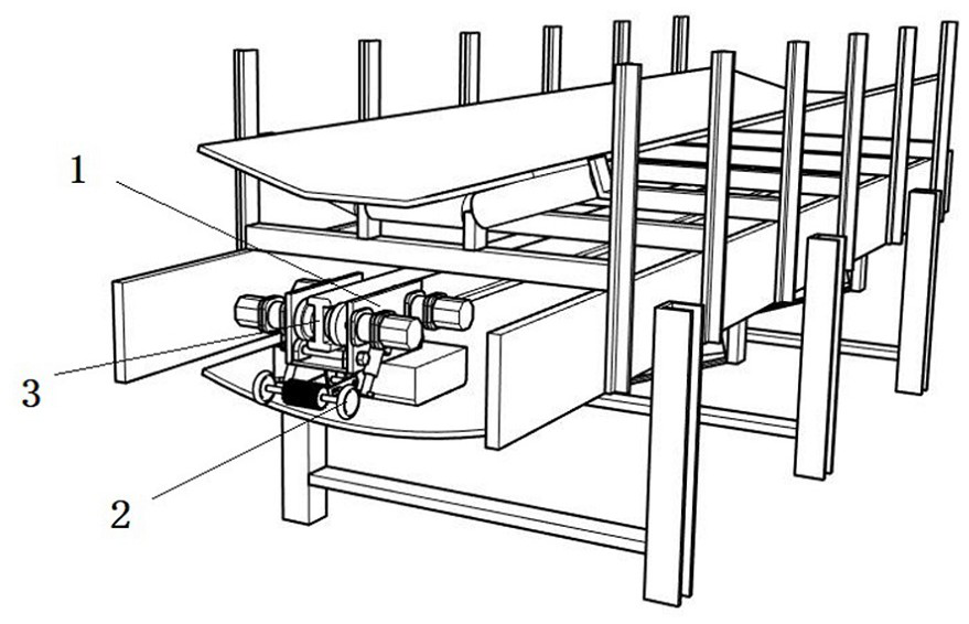
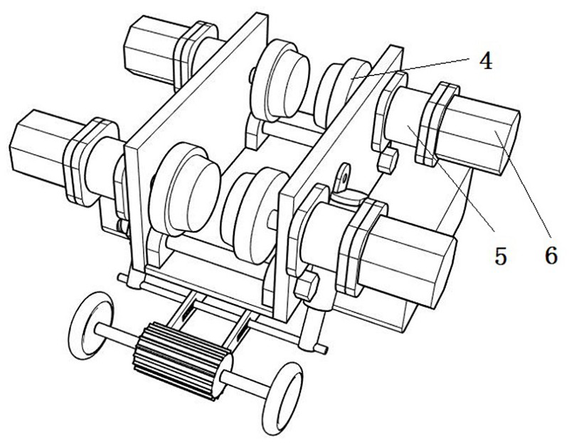
[0040] Embodiment 1, the self-charging device includes a first generator 10 and a first drive wheel 11 matched with the drive shaft of the first generator 10; The other end is hinged with the lifting lug 13; the lifting lug 13 is fixed on the lower side of the vehicle frame 1; a slideway 14 is provided on the swing rod 12; a jacking shaft 16 is horizontally set on the push head of the first push rod 15 push rod; The top shaft 16 is slidably matched with the slideway 14; the slideway 14 is provided with a buffer device that presses the top shaft 16; the first push rod 15 is hinged on the side wall of the vehicle frame 1; by changing the length of the first push rod 15, To control the rotation angle of the pendulum 12 and the hanger 13 ears, the first driving wheel 15 is closely attached to and separated from the belt of the tape machine; when the first driving wheel 11 is close to the belt of the tape machine; the top shaft 16 moves to the sliding The middle position of the tra...
Embodiment 2
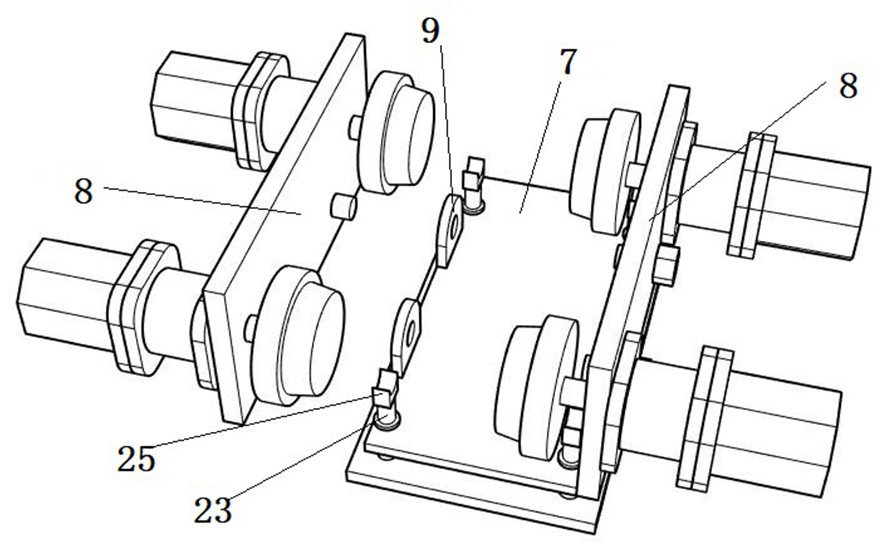
[0043] Embodiment 2, the self-charging device includes a second push rod 20, a second generator 21 and a pressure plate 22, the pressure plate 22 is arranged on the lower side of the vehicle frame 1, and the pressure plate 22 is provided with a speed reducer. The output shaft position of 5 corresponds to the compression column 23, and the bottom of the vehicle frame 1 is correspondingly provided with an installation channel 24; the compression column 23 passes through the installation channel 24 and is fixed with the compression block 25; the pressure plate 22 and the vehicle frame 1 Compression spring 26 is worn on the compression column 23 between; The spacing between pressure plate 22 and vehicle frame 1 is greater than the spacing between compression block 25 and the output shaft of speed reducer 5; When holding the output shaft of the speed reducer 5, the compression column 23 on one side of the compression spring 26 still has remaining space; the compression column 12 is ...
PUM
 Abstract
Description
Claims
Application Information
 - R&D
- Intellectual Property
- Life Sciences
- Materials
- Tech Scout
- Unparalleled Data Quality
- Higher Quality Content
- 60% Fewer Hallucinations
Browse by: Latest US Patents, China's latest patents, Technical Efficacy Thesaurus, Application Domain, Technology Topic, Popular Technical Reports.
© 2025 PatSnap. All rights reserved.Legal|Privacy policy|Modern Slavery Act Transparency Statement|Sitemap|About US| Contact US: help@patsnap.com


