Check patentability & draft patents in minutes with Patsnap Eureka AI!

Elevator landing door unlocking device and elevator landing door

A lock device and elevator floor technology, applied in the field of elevators, can solve problems such as failure to unlock, fatigue of the wire rope, separation of the lock rod and the lock seat, etc., and achieve the effect of reducing the difficulty of unlocking and ensuring stability

Pending Publication Date: 2022-08-09
HITACHI ELEVATOR CHINA
View PDF0 Cites 0 Cited by
  • Summary
  • Abstract
  • Description
  • Claims
  • Application Information

AI Technical Summary

Problems solved by technology

However, as the height of the landing door increases, the length of the lever is required to be longer. When the landing door is unlocked, when the rotation angle of the lever and the lever increases to a certain extent, the risk of separation of the locked lever and the lock seat is likely to occur. Failed to unlock
[0004] For the wire rope unlocking method, as the number of times of unlocking increases, the wire rope will be fatigued, and there is a risk of breaking when the wire rope reaches the number of life spans, resulting in failure to unlock

Method used


Image

  • Elevator landing door unlocking device and elevator landing door
  • Elevator landing door unlocking device and elevator landing door
  • Elevator landing door unlocking device and elevator landing door

Examples


Embodiment Construction

[0029] In order to make the above objects, features and advantages of the present invention more clearly understood, the specific embodiments of the present invention will be described in detail below with reference to the accompanying drawings. In the following description, numerous specific details are set forth in order to provide a thorough understanding of the present invention. However, the present invention can be implemented in many other ways different from those described herein, and those skilled in the art can make similar improvements without departing from the connotation of the present invention. Therefore, the present invention is not limited by the specific embodiments disclosed below.

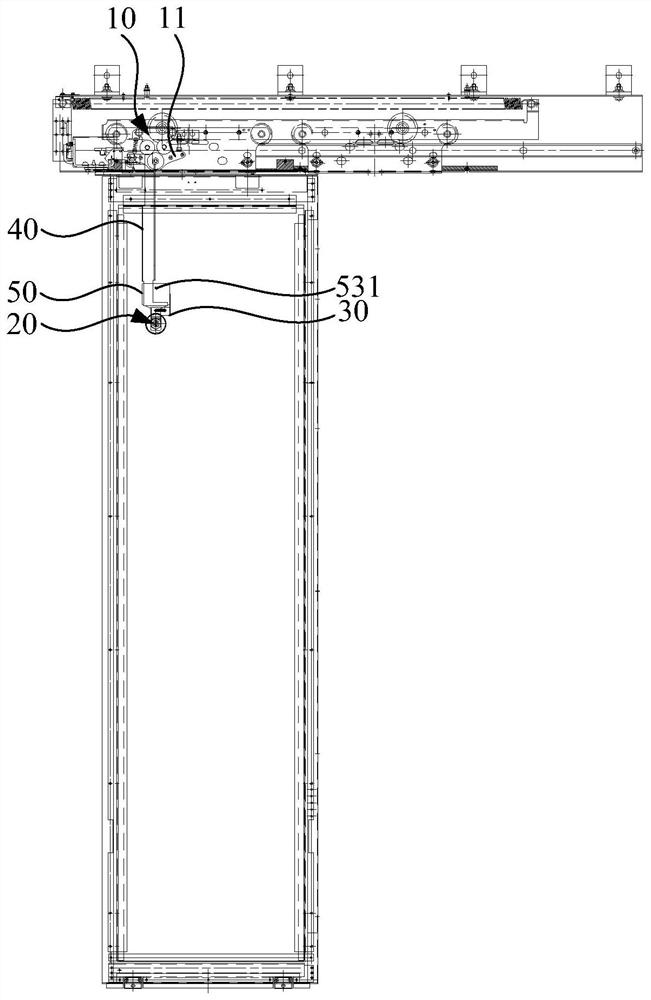
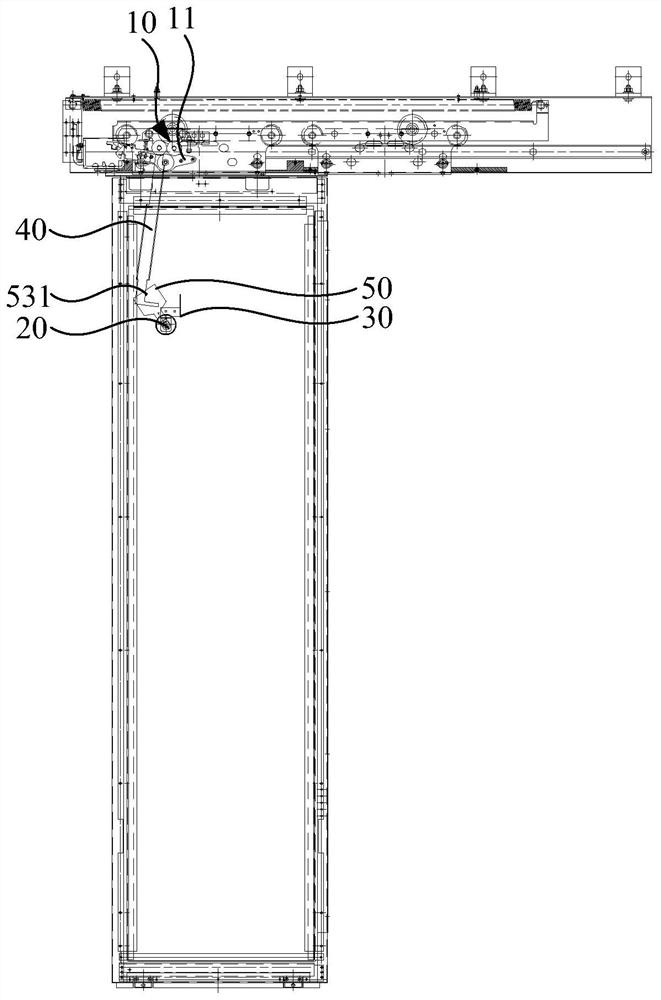
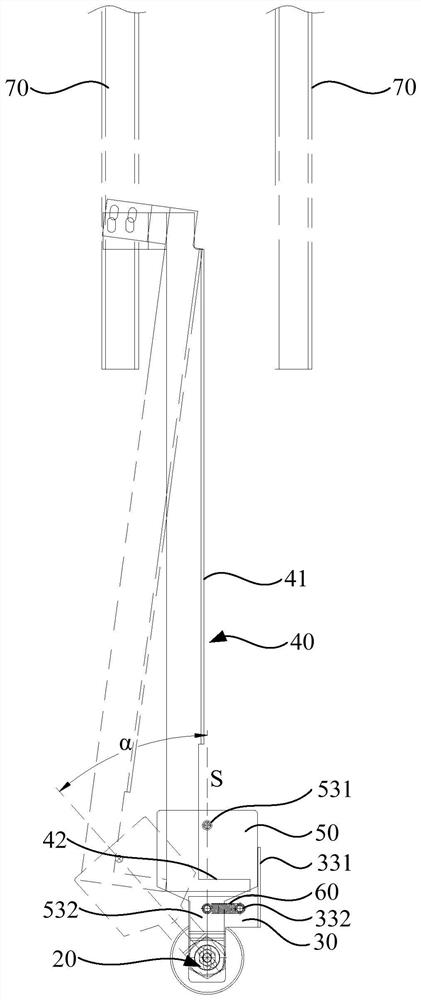
[0030] see figure 1 , image 3 , Figure 4 and Figure 5 , An elevator landing door unlocking device according to an embodiment of the present invention includes a landing door lock assembly 10 , a triangular lock assembly 20 , an unlocking lever 40 and a lock lever block 5...


PUM


Abstract

The invention relates to an elevator landing door unlocking device and an elevator landing door. The elevator landing door unlocking device comprises a landing door lock assembly, a triangular lock assembly, an unlocking deflector rod and a lock rod blocking seat. The triangular lock assembly comprises a lock body and a lock shaft rotationally connected with the lock body, and the lock shaft can rotate around the axial direction of the lock body relative to the lock body. The lock rod blocking seat is connected to the lock shaft and can synchronously rotate along with the lock shaft. One end of the unlocking deflector rod is connected to the landing door lock hook, the other end of the unlocking deflector rod extends to the rotating path of the lock rod blocking base, and the lock rod blocking base can be matched with the unlocking deflector rod in an abutting mode when rotating to drive the unlocking deflector rod to rotate so that the landing door lock hook can be rotationally opened. In this way, the unlocking part is prevented from being separated from the range where the unlocking deflector rod is located in the unlocking process, it is guaranteed that the landing door can be smoothly unlocked, the unlocking difficulty is reduced, meanwhile, the lock rod blocking base can play a role in blocking the unlocking deflector rod, the situation that the unlocking deflector rod generates vertical wind pressure in the vertical operation process of a lift car to form landing door lock assembly unlocking torque is avoided, and the safety of the lift car is improved. And the landing door lock assembly is instantaneously broken, so that the elevator is suddenly stopped.

Description

technical field [0001] The invention relates to the technical field of elevators, in particular to an elevator landing door unlocking device and an elevator landing door. Background technique [0002] The elevator floor door unlocking device is generally set on the door panel or the door cover beam. When the person outside the hall needs to open the elevator floor door, turn the triangular key, and drive the floor door lock to open through the structure of the pick, wire rope connection, etc. [0003] For the paddle type unlocking method, the paddle is driven by the rotation of the triangular lock cylinder, and the paddle drives the paddle just connected to the landing door lock hook to rotate, so that the landing door lock is opened. However, as the height of the landing door increases, the required lever length is longer. When the landing door is unlocked, when the rotation angle of the paddle and the lever increases to a certain extent, it is easy to cause the risk of sep...

Claims


Application Information

Patent Timeline
IPC IPC(8): B66B13/14E05B15/00E05B65/00
CPCB66B13/14E05B15/00E05B65/00
Inventor 霍俊超肖永恒丁建波
Owner HITACHI ELEVATOR CHINA
Features
  • R&D
  • Intellectual Property
  • Life Sciences
  • Materials
  • Tech Scout
  • Unparalleled Data Quality
  • Higher Quality Content
  • 60% Fewer Hallucinations
Learn More