
Speed limiting protection device for wind driven generator

A technology for wind generators and protection devices, which is applied in the control of wind turbines, the combination of wind turbines, and wind motors, etc., and can solve the problems of rotation rod adjustment, damage, and insufficient speed limit effect, and achieve the effect of protecting the rotation rod

Pending Publication Date: 2022-08-09
谢建刚
View PDF0 Cites 0 Cited by
  • Summary
  • Abstract
  • Description
  • Claims
  • Application Information

AI Technical Summary

Problems solved by technology

[0004] The purpose of the present invention is to solve the shortcomings in the prior art, such as: the speed limit effect is insufficient, it is difficult to adjust it according to the rotation speed of the rotating rod, the protection effect is lacking, and the rotating rod may also be damaged when the wind blows directly. damage, and proposed a speed limiting protection device for wind turbines

Method used


Image

  • Speed limiting protection device for wind driven generator
  • Speed limiting protection device for wind driven generator
  • Speed limiting protection device for wind driven generator

Examples


Embodiment Construction

[0018] The technical solutions in the embodiments of the present invention will be clearly and completely described below with reference to the accompanying drawings in the embodiments of the present invention. Obviously, the described embodiments are only a part of the embodiments of the present invention, but not all of the embodiments.

[0019] In the description of the present invention, it should be understood that the terms "upper", "lower", "front", "rear", "left", "right", "top", "bottom", "inside", " The orientation or positional relationship indicated by "outside" is based on the orientation or positional relationship shown in the accompanying drawings, and is only for the convenience of describing the present invention and simplifying the description, rather than indicating or implying that the indicated device or element must have a specific orientation, so as to The specific orientation configuration and operation are therefore not to be construed as limitations of...


PUM


Abstract

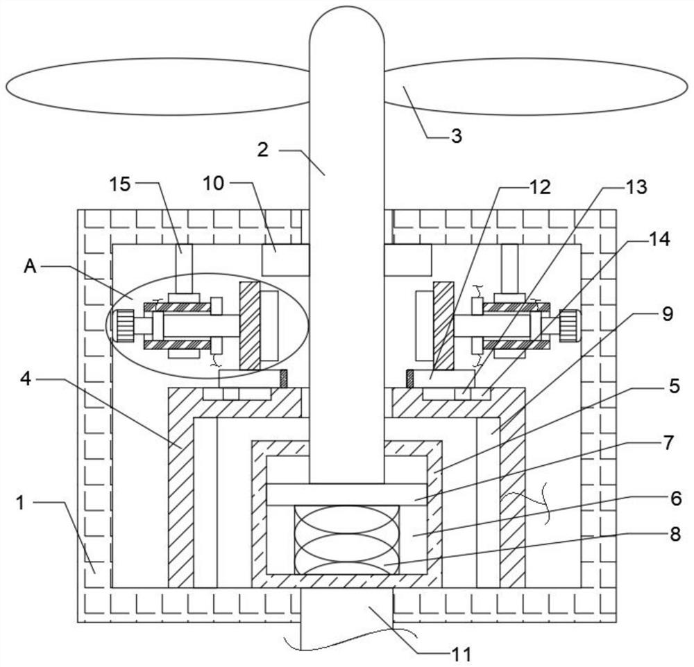
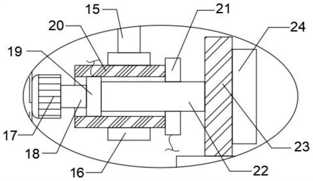
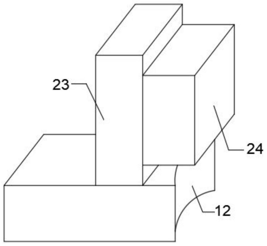
The speed limiting protection device comprises a fixed shell, a speed limiting box is fixedly connected to the interior of the fixed shell, a fixed block is rotationally arranged on the lower inner wall of the speed limiting box, a rotating rod is slidably connected to the fixed block, and a rotating shaft is arranged on the rotating rod. The rotating rod penetrates through the speed limiting box and the upper inner wall of the fixed shell and extends out of the fixed shell, a plurality of fixed impellers are fixedly connected to the side wall of the end, located on the outer side of the fixed shell, of the rotating rod, a connecting rod is fixedly connected to the other end of the fixed block, and the connecting rod penetrates through the lower inner wall of the fixed shell. The rotating rod can be adjusted according to the rotating speed of the rotating rod, the force applied to the rotating rod is not changed when the rotating rod is subjected to speed limiting, speed limiting is facilitated, the rotating rod can be retracted into the fixed shell when wind power is too large, it is avoided that the rotating rod is excessively exposed to the outer side, and therefore the effect of protecting the rotating rod is achieved.

Description

technical field [0001] The invention relates to the field of wind power generation, in particular to a speed limiting protection device for wind power generators. Background technique [0002] With the development of the times, people's application of clean energy is becoming more and more common, and wind power is a kind of clean energy, which is widely used in western my country. The rotor rotates and finally outputs the electrical equipment of alternating current. [0003] When the wind turbine is too strong, the rotating speed of the rotating rod is too fast, which may cause damage to the rotating rod, so it needs to be limited in speed. Adjusting the rotation speed is not conducive to the speed limit of the rotation. At the same time, the protection effect of the speed limit device on the rotating rod is lacking, and the rotating rod may also be damaged when the wind blows directly. SUMMARY OF THE INVENTION [0004] The purpose of the present invention is to solve th...

Claims


Application Information

Patent Timeline
Patent Type & Authority Applications(China)
IPC IPC(8): F03D7/02F03D9/25
CPCF03D7/0248F03D9/25F05B2270/101F05B2270/327Y02E10/72
Inventor 谢建刚
Owner 谢建刚
Learn More