Hydraulic valve with long service life

A hydraulic valve with a long service life technology, applied in the field of hydraulic valves, can solve the problems of reducing the service life of hydraulic valves, achieve the effect of increasing service life, reducing water hammer effect, and ensuring normal use

Active Publication Date: 2022-08-09
博顿液压股份有限公司
View PDF6 Cites 2 Cited by
  • Summary
  • Abstract
  • Description
  • Claims
  • Application Information

AI Technical Summary

Problems solved by technology

[0002] The hydraulic valve is an automatic component operated by pressure oil. It is controlled by the pressure oil of the pressure distribution valve and can be used to control the on-off of the system. It is often used in oil circuits such as clamping, control, and lubrication; Cooperate to realize fast opening and closing, but due to the high speed, water hammer effect will be generated at the moment of closing and blocking the water flow. This impact force will act on the valve body, valve core and other parts for a long time, which will reduce the service life of the hydraulic valve. During the use of time, the impurities in the oil or the colloid precipitated due to oxidation are adsorbed on the inner wall of the hydraulic valve, which affects the use of the hydraulic valve. Therefore, a hydraulic valve with a long service life is proposed.

Method used


Image

  • Hydraulic valve with long service life
  • Hydraulic valve with long service life
  • Hydraulic valve with long service life

Examples


Embodiment Construction

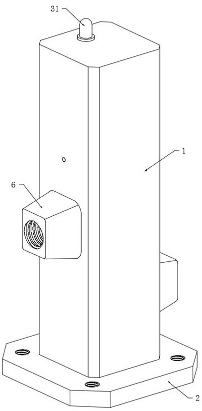
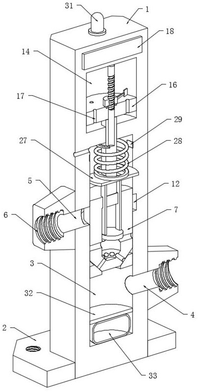
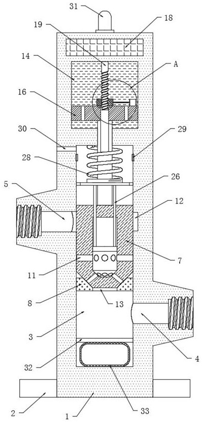
[0021] refer to Figure 1-5 , a hydraulic valve with a long service life, including a valve body 1, the lower end of the valve body 1 is fixedly connected with a mounting seat 2, a cylindrical valve cavity 3 is opened inside the valve body 1, and the outer wall of the valve body 1 is close to the lower end. A water inlet 4 is opened on the upper part to communicate with the valve cavity 3, and a water outlet 5 is opened in the middle of the outer wall of the valve body 1 away from the water inlet 4 to communicate with the valve cavity 3. The valve body 1 is located on the outer walls of the water inlet 4 and the water outlet 5. A connecting valve block 6 is fixed to the valve cavity 3 , a valve core 7 is sealed and slidably connected in the valve cavity 3 , and a constant pressure hole 30 is opened on the outer wall of the valve body 1 to communicate with the top cavity wall of the valve cavity 3 .

[0022] In the valve cavity 3, a baffle 8 is sealed and fixedly connected to t...


PUM


Abstract

The hydraulic valve long in service life comprises a valve body, the lower end of the valve body is fixedly connected with a mounting base, a cylindrical valve cavity is formed in the valve body, and a water inlet is formed in the outer wall of the side, close to the lower end, of the valve body and communicates with the valve cavity; a water outlet is formed in the middle of the outer wall of the side, away from the water inlet, of the valve body and communicated with the valve cavity, and connecting valve blocks are fixed to the outer walls, located on the water inlet and the water outlet, of the valve body. The water hammer effect is reduced by prolonging the opening time of the valve element to prevent the valve element from instantaneously blocking water flow, meanwhile, the water hammer effect is weakened through an air spring jointly composed of the elastic air bag and the partition plate, the service life of the hydraulic valve is prolonged, water pressure is detected in the process that the hydraulic valve is opened for water passing, and the safety of the hydraulic valve is improved. The hydraulic valve is prevented from working in an overpressure water flow state, and when the hydraulic valve is opened and closed, impurities or colloids adhered to the wall of the control cavity are scraped off through rotation of the scraping plate, so that normal use of the hydraulic valve is guaranteed.

Description

technical field [0001] The invention relates to the technical field of hydraulic valves, in particular to a hydraulic valve with long service life. Background technique [0002] Hydraulic valve is an automatic component operated with pressure oil. It is controlled by the pressure oil of the pressure distribution valve and can be used to control the on-off of the system. It is often used in oil circuits such as clamping, control, and lubrication. Cooperate to achieve quick opening and closing, but due to the high speed, the water hammer effect will be generated at the moment of closing the blocked water flow. This impact force acts on the valve body, valve core and other parts for a long time, which will reduce the service life of the hydraulic valve, and the hydraulic valve will be used for a long time. In the course of time use, impurities in the oil or colloid precipitated by oxidation are adsorbed on the inner wall of the hydraulic valve, which affects the use of the hydr...

Claims


Application Information

Patent Timeline
Patent Type & Authority Applications(China)
IPC IPC(8): F16K1/00F16K31/06F16K47/02F16K47/00F16K37/00F16K27/02G01L19/12B08B9/04
CPCF16K1/00F16K31/0655F16K47/023F16K47/0111F16K37/005F16K27/029F16K27/0254G01L19/12B08B9/04Y02E10/20
Inventor 李莉
Owner 博顿液压股份有限公司
Why Eureka
Try Eureka