

Display device
A technology of display device and liquid crystal display panel, which is applied in the directions of instruments, nonlinear optics, optics, etc., can solve the problem of the width of the frame of the display device, etc., and achieve the effect of reducing the width
- Summary
- Abstract
- Description
- Claims
- Application Information
AI Technical Summary
Problems solved by technology
Method used
Image

Examples
Embodiment 1
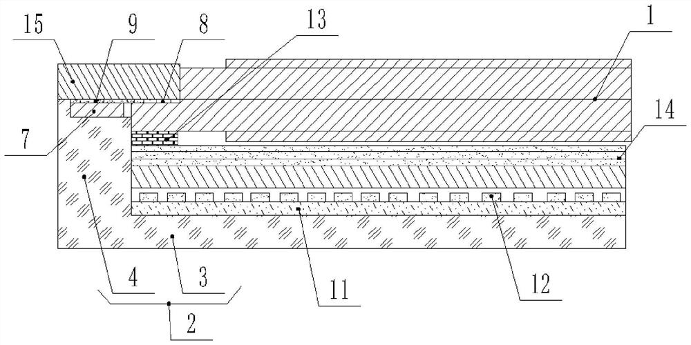
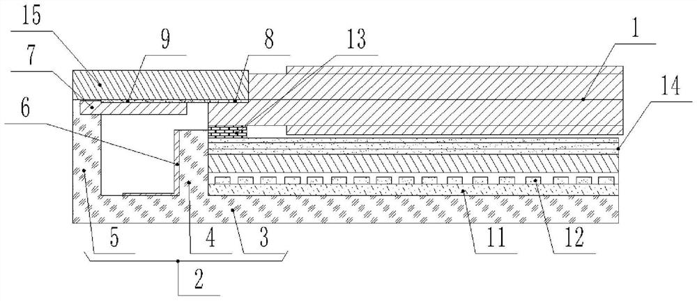
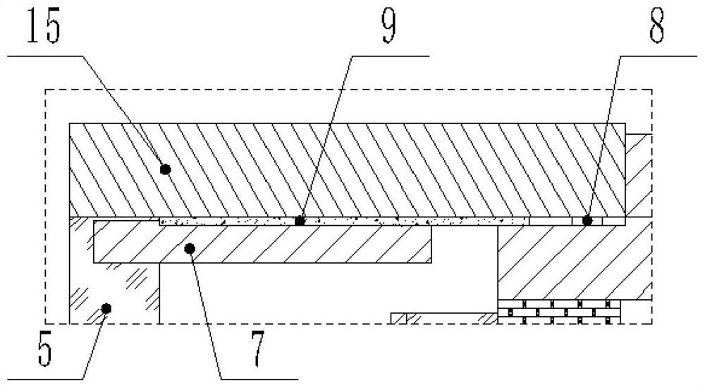
[0034] figure 1 A schematic structural diagram of a display device is shown in Embodiment 1 of the present application; figure 2 A schematic structural diagram of yet another display device is shown in Embodiment 1 of the present application; image 3 Yes figure 2 A partial magnified view of .
[0035] like Figure 1 to Figure 3 , an embodiment of the present application provides a display device, including: a matching backlight module, a liquid crystal display panel 1, and a driving component, wherein the driving component includes: a matching PCB substrate 7 and an IC chip 8, and the PCB substrate 7 is provided with At the position close to the side wall of the liquid crystal display panel 1, one end of the IC chip 8 is electrically connected to the liquid crystal display panel 1 through the flexible circuit board 9, and the other end is electrically connected to the PCB substrate 7, wherein the IC chip 8 is used to drive the liquid crystal display panel. A driver IC f...
Embodiment 2
[0049] Figure 4 A schematic structural diagram of a display device is shown in Embodiment 2 of the present application; Figure 5 Yes Figure 4 A partial enlarged view of ; Image 6 It is a schematic structural diagram of the cooperation among the flexible circuit board 9 , the IC chip 8 and the PCB substrate 7 in the second embodiment.
[0050] like Figure 4 to Figure 7 , the embodiment of the present application also provides a display device, which is similar to the display device of the first embodiment, the difference is that the IC chip 8 is mounted on the flexible circuit board 9, and the IC chip 8 is mounted on the PCB through the flexible circuit board 9 The wall surface on the substrate 7 that is perpendicular to the front frame 15 , in other words, the IC chip 8 is mounted on the flexible circuit board 9 to form a chip-on film. The end of the IC chip 8 is electrically connected to the PCB substrate 7; more specifically, such as Image 6 As shown, in order to ...
Embodiment 3
[0052] Figure 7 A schematic structural diagram of a display device is shown in Embodiment 3 of the present application; Figure 8 Yes Figure 7 A partial enlarged view of ; Figure 9 Embodiment 3 of the present application shows a schematic structural diagram of yet another display device.
[0053] like Figure 7 to Figure 9 , the embodiment of the present application also provides a display device, which is similar to the display device of the first embodiment, the difference is that the liquid crystal display panel 1 is set as a double-layer liquid crystal cell, and the liquid crystal display panel 1 is stacked on the back of the backlight module. On the light-emitting side, the two driving components are disposed near the side wall of the liquid crystal display panel 1 , and the two driving components are electrically connected to different liquid crystal cells correspondingly.
[0054] Further, the two drive assemblies are connected by a flexible connector 16, and mor...
PUM
 Abstract
Description
Claims
Application Information