Deflection coil and colour cathode-ray tube fitted with same
A cathode ray tube and deflection yoke technology, applied in the direction of cathode ray tube/electron beam tube, electrode device and related components, discharge tube, etc., can solve the deformation of winding material, abnormal stretching of winding material of coil, and damage of winding material And other issues
- Summary
- Abstract
- Description
- Claims
- Application Information
AI Technical Summary
Problems solved by technology
Method used
Image
Examples
no. 1 Embodiment
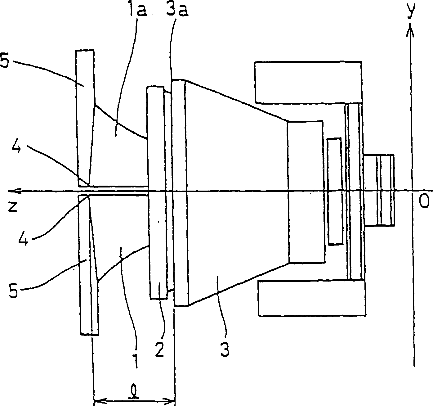
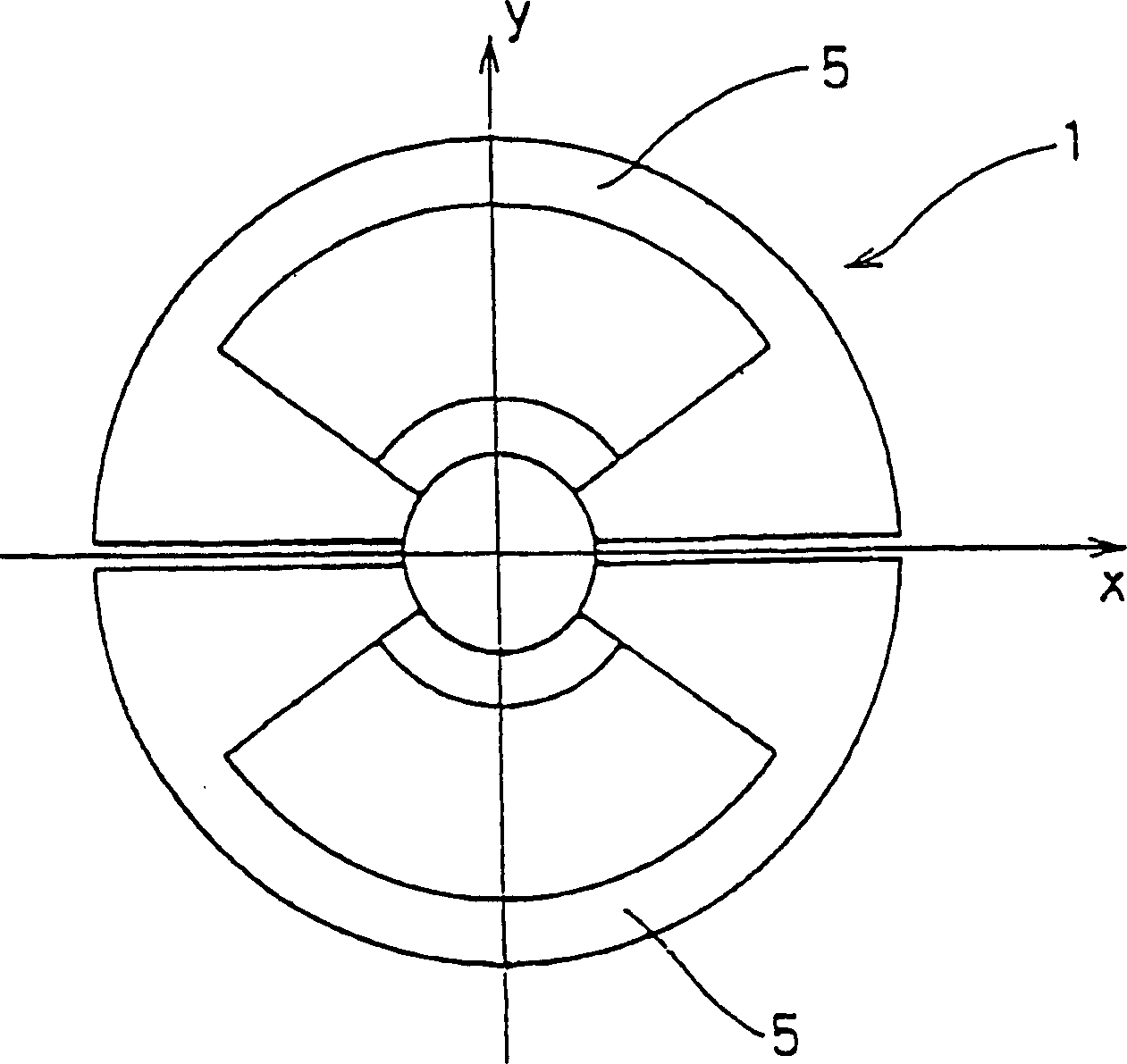
[0085] figure 1 It is a side view showing the first embodiment of the deflection yoke related to the present invention, figure 2 from the side of the screen figure 1 A view of the deflection yoke shown in . like figure 1 As shown in , the deflection yoke consists of a saddle-shaped horizontal deflection coil 1, a saddle-shaped vertical deflection coil 2 disposed outside the horizontal deflection coil 1, and a ferrite core 3 disposed outside the vertical deflection coil 2. constitute.
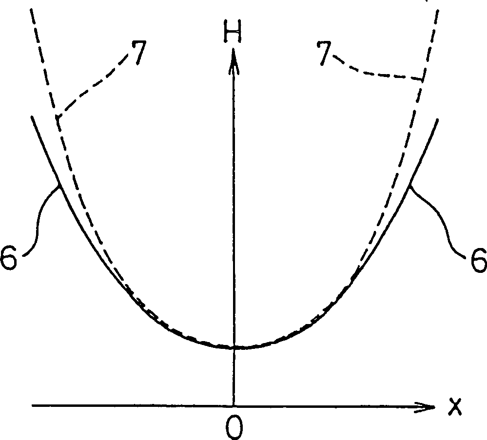
[0086] The tapered portion 1a on the screen side of the horizontal deflection coil 1 is wound within a winding angle range of 1° to 80° with respect to the horizontal axis, particularly with a winding angle focused on 18° to 30° Winding distribution in angular range. Here, the "winding angle" refers to the area occupied by the winding of the deflection yoke viewed from the screen side, in terms of an angle away from the horizontal axis (X-axis). Also, its maximum protrusion point 4 in the...
no. 2 Embodiment
[0094] Image 6 It is a plan view showing a second embodiment of the color cathode ray tube according to the present invention. like Image 6 As shown, the color cathode ray tube body 9 is composed of a glass panel 10 and a glass funnel part 11 connected to the rear of the glass panel 10, and an electron gun (not shown) is arranged at the rear of the glass funnel part 11. In addition, a horizontal deflection coil 1 wound into a saddle shape, a saddle-type vertical deflection coil 2 provided outside the horizontal deflection coil 1, and an iron coil 2 provided outside the vertical deflection coil 2 are mounted on the rear periphery of the glass funnel portion 11. Oxygen core 3 constitutes the deflection coil. The cone portion 1a on the screen side of the horizontal deflection coil 1 is wound within a winding angle range of 1° to 80° based on the horizontal axis, especially with a winding angle focusing on 18° to 30°. Winding distribution in line angle range. Further, the po...
no. 3 Embodiment
[0098] Figure 7 It is a plan view showing the third embodiment of the deflection yoke related to the present invention, Figure 8 From Figure 7 Cross-sectional view viewed in the VIII-VIII direction. like Figure 7 As shown, the deflection yoke is composed of a saddle-shaped horizontal deflection coil 12, a saddle-shaped vertical deflection coil 13 arranged outside the horizontal deflection coil 12, and a ferrite core 14 arranged outside the vertical deflection coil 13. .
[0099]The tapered portion 13a on the screen side of the vertical deflection yoke 13 is wound within a winding angle range of 1° to 80° with respect to the vertical axis. In particular, there is a winding distribution that focuses on the winding angle range of 18° to 30°. And the position of its maximum protruding point 15 along the tube axis direction is fixed at the front end portion 14a20mm away from the ferrite core 14 screen side, moreover, with the cone portion 13a of the vertical deflection coi...
PUM
 Abstract
Description
Claims
Application Information
 - R&D
- Intellectual Property
- Life Sciences
- Materials
- Tech Scout
- Unparalleled Data Quality
- Higher Quality Content
- 60% Fewer Hallucinations
Browse by: Latest US Patents, China's latest patents, Technical Efficacy Thesaurus, Application Domain, Technology Topic, Popular Technical Reports.
© 2025 PatSnap. All rights reserved.Legal|Privacy policy|Modern Slavery Act Transparency Statement|Sitemap|About US| Contact US: help@patsnap.com


