Eureka AIR delivers breakthrough ideas for toughest innovation challenges, trusted by R&D personnel around the world.

Acousto-optic element, light deflector light beam scanner and image recording device

An acousto-optic component and acousto-optic deflection technology, applied in electrical components, instruments, optics, etc., can solve the problems of cost increase and size increase

Inactive Publication Date: 2004-06-30
FUJIFILM CORP
View PDF0 Cites 0 Cited by
  • Summary
  • Abstract
  • Description
  • Claims
  • Application Information

AI Technical Summary

Problems solved by technology

[0006] However, in the OFF-[110] type optical deflection element, since the propagation direction of the ultrasonic wave is greatly inclined to the [110] axis direction, the TeO used as the acousto-optic element 2 The size of the crystal must be larger than before, so there is a problem of increasing the cost
[0007] At the same time, in the beam scanning device, when it is desired to perform two-dimensional correction (movement) of the beam irradiation position to the irradiated object, it can be considered to combine two AODs in series along the optical path of the beam, and configure the two AODs to The beam deflection directions are orthogonal to each other (tandem configuration), but the problem of increased cost as mentioned above will be more prominent

Method used


Image

  • Acousto-optic element, light deflector light beam scanner and image recording device
  • Acousto-optic element, light deflector light beam scanner and image recording device
  • Acousto-optic element, light deflector light beam scanner and image recording device

Examples


Embodiment Construction

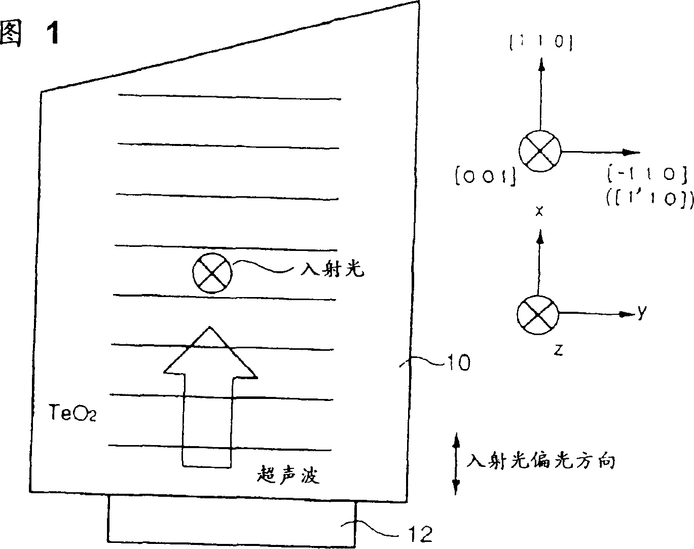
[0083] Hereinafter, embodiments of the first invention will be described in detail with reference to the drawings. First, the application of the present invention to the use of TeO 2 The case of a single crystal ON-[110] type deflector (AOD). As shown in Fig. 1, the AOD consists of the head beveled TeO 2 Single crystal 10 and converter 12, the converter 12 is pasted on TeO 2 The bottom of the single crystal is used to generate transverse ultrasonic waves that propagate along the [110] direction of the crystal and deviate toward the [1'10] direction. In TeO 2 The head of the single crystal can also be pasted with sound-absorbing material (not shown in the figure).

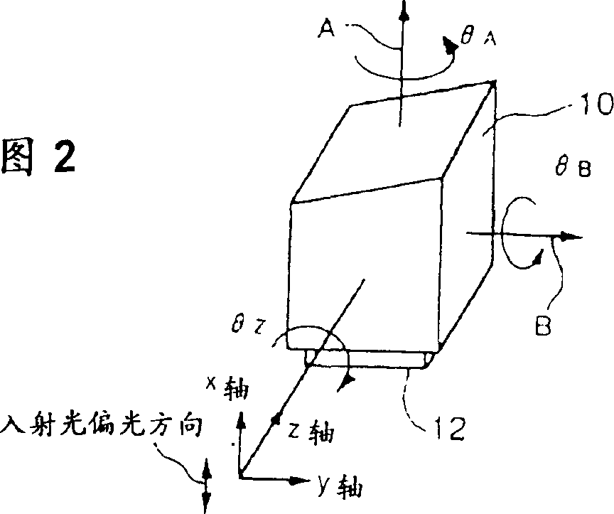
[0084] In addition, as shown in Figure 1 and Figure 2, determine the xyz coordinates that make the z-axis coincide with the propagation direction of the incident light, the x-axis coincide with the polarization direction of the incident light, and the y-axis is determined by the x-axis and z-axis according to th...


PUM


Abstract

An xyz coordinate system is determined so that a z-axis may coincide with an incident direction of an incident light, an x-axis may coincide with a polarizing direction of the incident light and a y-axis may be defined as the right-handed system from the z-axis and x-axis. An acousto-optic element is rotated around the z-axis, around the axis in a direction of propagation of an ultrasonic wave and around an axis perpendicular to a plane formed by the z-axis and the direction of propagation of the ultrasonic wave, so that the attitude of the acousto-optic element to the incident light is adjusted.

Description

technical field [0001] The invention relates to an acousto-optic element, an optical deflector, a light beam scanning device and an image recording device, in particular to an acousto-optic element (AOM) or an acousto-optic deflector (AOD) utilizing the acousto-optic effect, and an optical deflection device. device, a light beam scanning device using the acousto-optic element and used in image recording or image reading, and an image recording device using the acousto-optic element for image recording. Background technique [0002] Conventionally, there is known an acousto-optic deflector (AcoustoOptic Deflector: hereinafter abbreviated as AOD) that deflects light by utilizing the acousto-optic effect. Such an AOD is arranged, for example, on the optical path of a beam of a beam scanning device, and is used for deflecting, for example, a scanning beam of a scanning device in advance by the AOD to correct the beam irradiation position on an irradiated object. [0003] Howeve...

Claims


Application Information

Patent Timeline
Patent Type & Authority Patents(China)
IPC IPC(8): G02F1/33H04N1/053H04N1/06H04N1/191
CPCH04N2201/04765H04N1/053H04N2201/04793H04N1/0607H04N1/0635G02F1/33H04N2201/0471H04N1/1911H04N2201/04794H04N2201/04786H04N2201/02439H04N2201/04734H04N2201/04724
Inventor 山下明子角克人
Owner FUJIFILM CORP
Why Eureka
Eureka Blog
Learn More