
Microwav eoven heater system

A technology for a heater and a microwave oven, applied in the field of microwave ovens, can solve the problem that the heater 7 is easily polluted by dirt, and achieve the effect of effective transmission

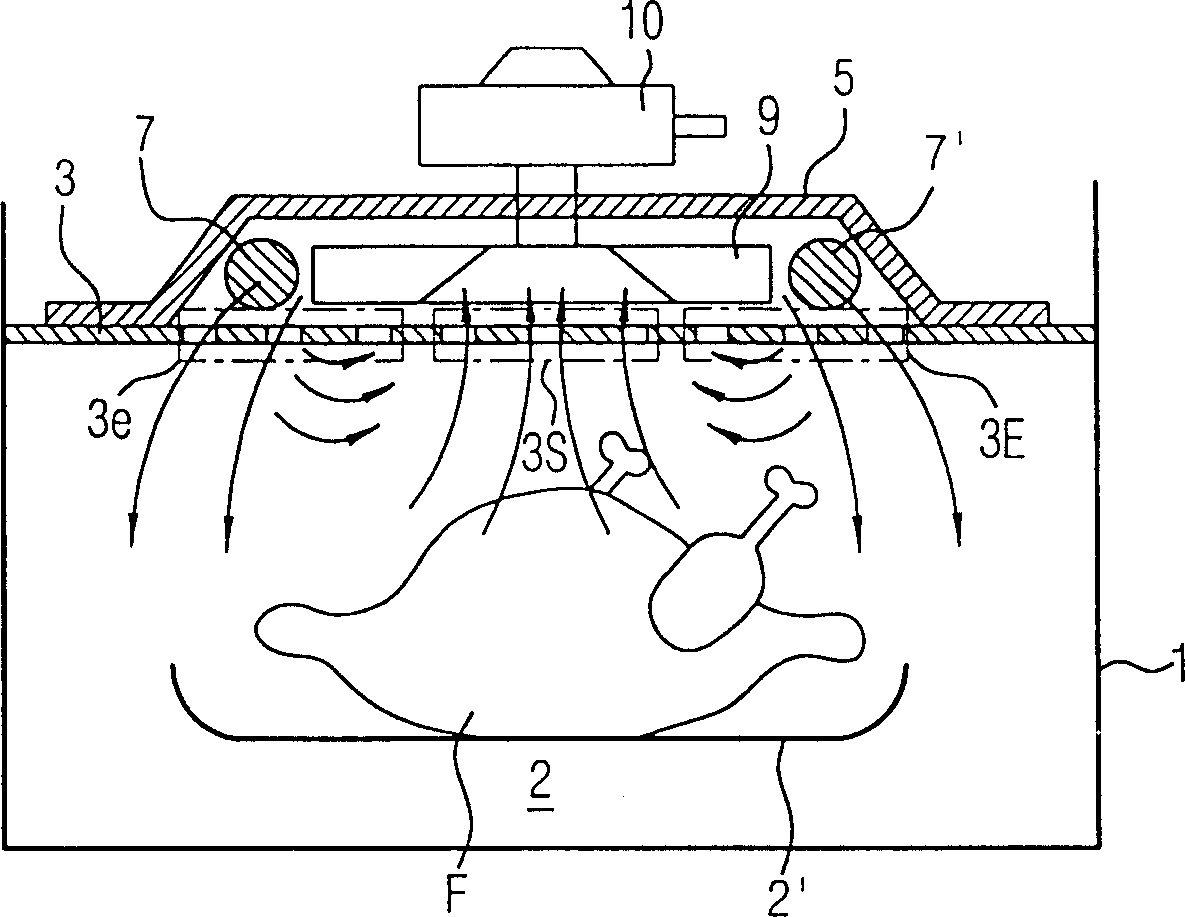
Inactive Publication Date: 2004-07-28
LG ELECTRONICS INC
View PDF0 Cites 1 Cited by
  • Summary
  • Abstract
  • Description
  • Claims
  • Application Information

AI Technical Summary

Problems solved by technology

Especially, since the food entrainment in the cooking chamber 2 may splash to the upper part of the cooking chamber 2, the heaters 7 and 7' are easily contaminated with dirt.

Method used


Image

  • Microwav eoven heater system
  • Microwav eoven heater system
  • Microwav eoven heater system

Examples


Embodiment Construction

[0026] Hereinafter, the heater system of the microwave oven of the present invention will be described with reference to the accompanying drawings.

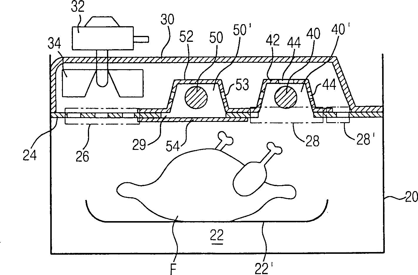
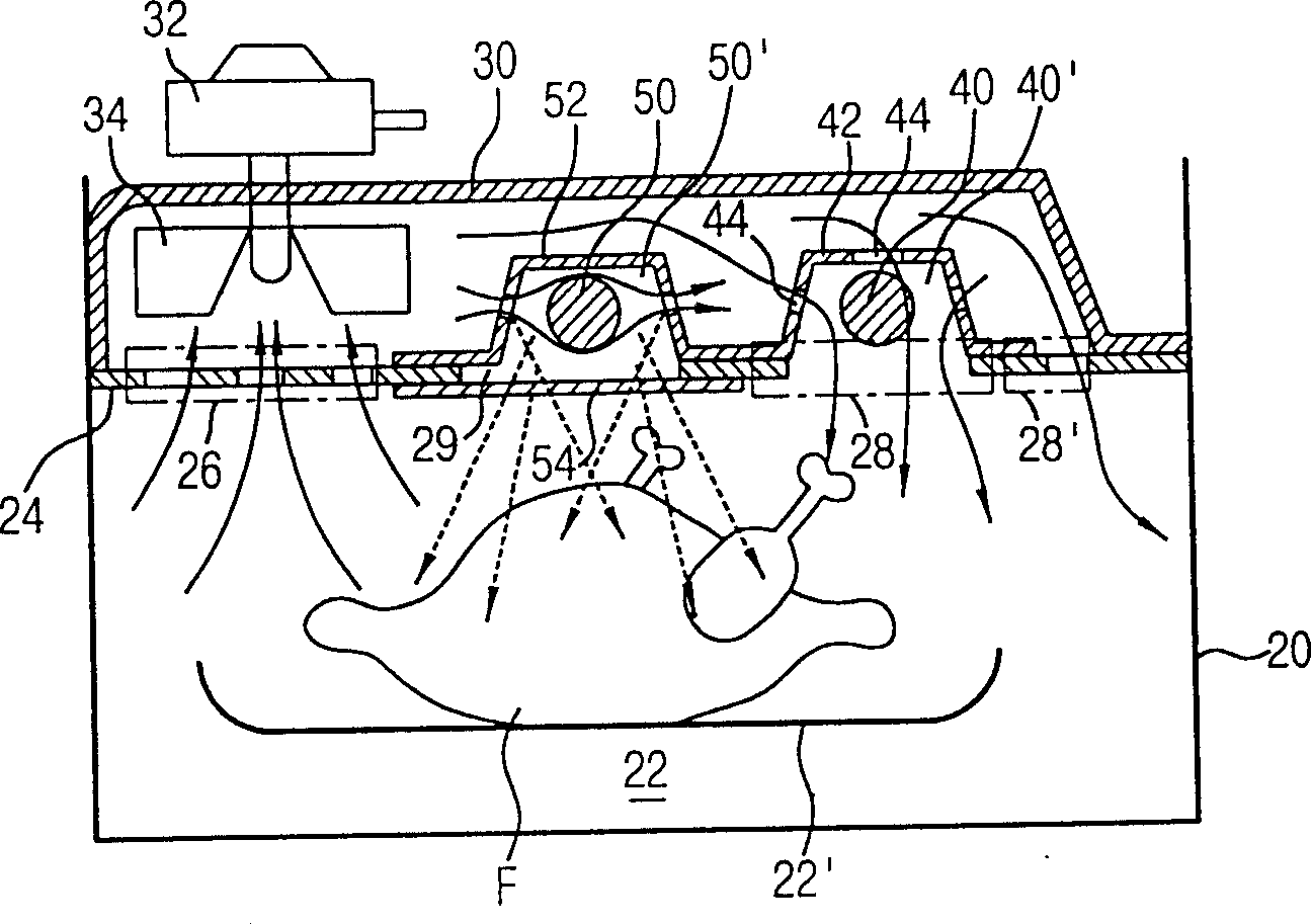
[0027] figure 2 It is a structural sectional view of the microwave oven heater system of the present invention.

[0028] Such as figure 2 As shown, a cooking chamber 22 is formed within the cavity 20 of the microwave oven. In the cooking chamber 22, cooking food F on a plate 22' is cooked by microwave energy supplied from a magnetron (not shown) mounted on an electric chamber (not shown) or heat generated by a heater system.

[0029] An upper plate 24 is formed on the upper surface of the cooking chamber 22 while the upper plate 24 constitutes the roof of the cooking chamber 22 . A suction part 26 and a discharge part 28 are respectively formed on the upper plate 24, the suction part 26 forms the airflow from the inside of the cooking chamber 22, and the discharge part 28 forms the airflow from the outside of the cooking cha...


PUM


Abstract

In a heater system for a microwave oven including an air tunnel having an suction portion and a discharge portion, formed at an upper surface of a cooking chamber, a fan assembly installed inside the air tunnel and having a circulation fan forming air flow by sucking air inside the cooking chamber through the suction portion and discharge the sucked air through the air tunnel and the discharge portion, a first heater chamber having a first heater installed inside the air tunnel and heating air discharged into the discharge portion from the air tunnel, and a second heater chamber having a second heater installed inside the air tunnel and emitting radiation heat into the cooking chamber, wherein the suction portion and the discharge portion are respectively formed at each end portions of the upper surface of the cooking chamber, said end portions facing each other and positioned toward the side walls of the cooking chamber.

Description

technical field [0001] The present invention relates to microwave ovens, and more particularly to a microwave oven heater system capable of more efficiently transferring heat from the heater to food being cooked. Background technique [0002] Microwave ovens use microwave energy to heat cooked food. Recently, in order to add various heating functions to microwave ovens, a heater is installed as another heating source in addition to microwave energy, and cooked food is heated with heat generated by this heater. [0003] figure 1 It is a structural cross-sectional view of a heater system of a microwave oven in the prior art. [0004] Such as figure 1 As shown, in the prior art microwave oven heater system, a cooking chamber 2 is formed in the cavity to cook food F placed on a plate 2'. [0005] An additional heating chamber 5 is formed on the top of the upper plate 3 forming the top of the cooking chamber 2, and heaters 7 and 7' for heating food on the dish 2' are installe...

Claims


Application Information

Patent Timeline
IPC IPC(8): F24C7/02F24C1/00H05B6/80
CPCH05B6/6473F24C7/02
Inventor 金锡泰柳盛允李根炯
Owner LG ELECTRONICS INC
Learn More