Back lighting device of LCD

A backlight device and light technology, applied in the direction of instruments, optics, nonlinear optics, etc., can solve the problems of increasing the display, increasing the area or thickness of the display, increasing the thickness of the display, etc., to achieve the effect of improving efficiency and reducing thickness

Inactive Publication Date: 2004-10-06
AU OPTRONICS CORP
View PDF1 Cites 0 Cited by
  • Summary
  • Abstract
  • Description
  • Claims
  • Application Information

AI Technical Summary

Problems solved by technology

However, these two solutions either increase the area of ​​the display or increase the thickness of the display
In today's trend of thin, light and small displays, the increase in display area or thickness is a major disadvantage

Method used


Image

  • Back lighting device of LCD
  • Back lighting device of LCD
  • Back lighting device of LCD

Examples


Embodiment Construction

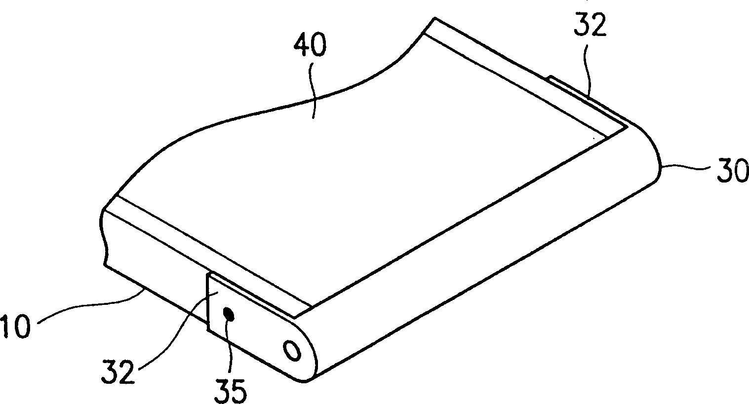
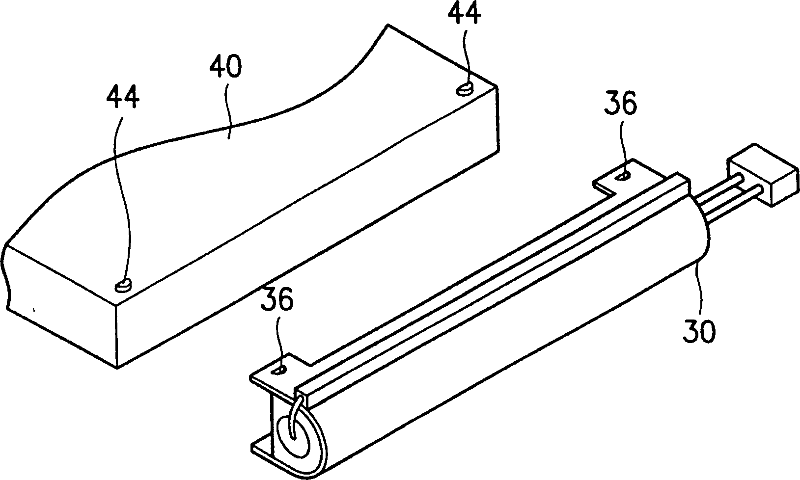
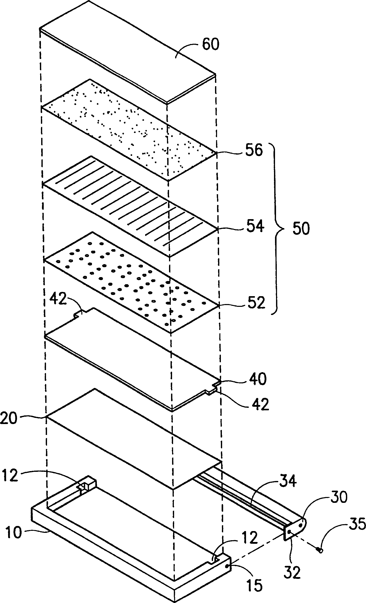
[0018] image 3 An exploded view of the backlight device of the present invention is shown. The backlight device can be applied in a liquid crystal display. Such as image 3 As shown, the backlight device of the present invention includes a light guide plate 100 , a reflector 200 , a reflector 300 and a lamp 340 . The reflective sheet 200 is disposed under the light guide plate 100 . The light guide plate 100 has a light guide surface 110 , a bottom surface 120 , a light incident side (not shown), a first locking side 130 and a second locking side 131 . The light guide surface 110 is close to the light incident surface 62 of a liquid crystal panel 60 , and the bottom surface 120 of the light guide surface is disposed above the reflection sheet 200 . The light guide plate 100 also includes first and second engaging structures 140, 141, the first and second engaging structures are two protrusions 140, 141, which are respectively arranged on the first and second engaging side...


PUM


Abstract

The back lighting device includes lightguide plate, reflecting hood and light source and the lightguide plate has a light incident side and two clamping sides with separate clamping structure. The reflecting hood beside the incident side of the lightguide plate has reflecting surface, opening toward the light incidence side, and two side su8pporting members extending toward the two clamping sides and with separate connecting structure to combine with one of the clamping structure separately.

Description

technical field [0001] The present invention relates to a backlight device, in particular to a backlight device with improved assembly efficiency, reduced light leakage and reduced thickness. Background technique [0002] Figure 1A A perspective view of a known backlight device of a liquid crystal display is shown. As shown in the figure, the known backlight device includes a frame 10 , a light guide plate 40 and a reflector 30 . The side surface 32 of the reflector 30 is fixed on the frame 10 by combining the screw 35 with the screw hole (not marked) on the frame 10 . [0003] Figure 1B is displayed Figure 1A An exploded view of the backlight unit. As shown in the figure, a reflective sheet 20 is disposed on the frame 10 . Then the light guide plate 40 is fixed on the reflection sheet 20 , and the pair of protrusions 42 on the light guide plate 40 are placed in the fixing groove 12 of the frame 10 . A lamp tube 34 is placed in the reflector 30 , and the two side sur...

Claims


Application Information

Patent Timeline
IPC IPC(8): G02F1/13357
Inventor 陈豪智
Owner AU OPTRONICS CORP
Why Eureka
Try Eureka