Equipment for calcinating cement clinker in large granule and fluidiazation

A calcination device and fluidization technology, applied in the field of large particle fluidized cement clinker calcination device, can solve the problems of unstable calcination thermal system, poor quality of cement clinker, uneven ventilation of moving bed shaft kiln, etc. Achieve the effect of small fluctuation, not easy to burst, and prolong the residence time

Inactive Publication Date: 2004-10-13
XI'AN UNIVERSITY OF ARCHITECTURE AND TECHNOLOGY
View PDF1 Cites 10 Cited by
  • Summary
  • Abstract
  • Description
  • Claims
  • Application Information

AI Technical Summary

Problems solved by technology

Due to the uniform distribution and close contact of the materials of various components in the large particles, the uniformity of the reaction at high temperature is ensured; the wind speed required for the fluidization of large particles is relatively large, and the fluidized bed has a small cross-sectional area, which reduces the firing rate of the original shaft kiln. The belt is changed from a moving bed to a fluidized bed, which can solve the problem of poor quality of cement clinker caused by uneven ventilation of the moving bed shaft kiln and unstable firing thermal system

Method used


Image

  • Equipment for calcinating cement clinker in large granule and fluidiazation
  • Equipment for calcinating cement clinker in large granule and fluidiazation
  • Equipment for calcinating cement clinker in large granule and fluidiazation

Examples


Embodiment Construction

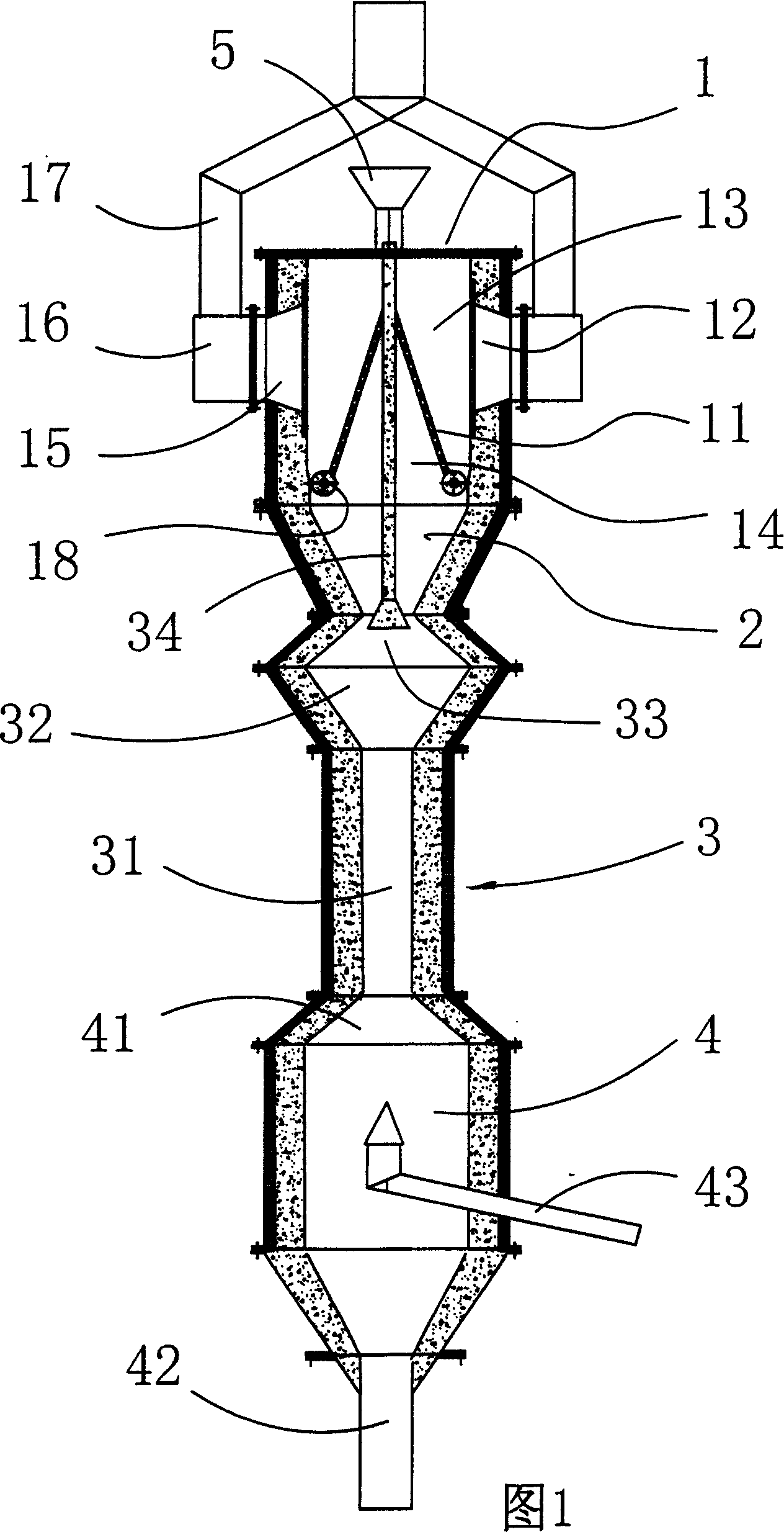
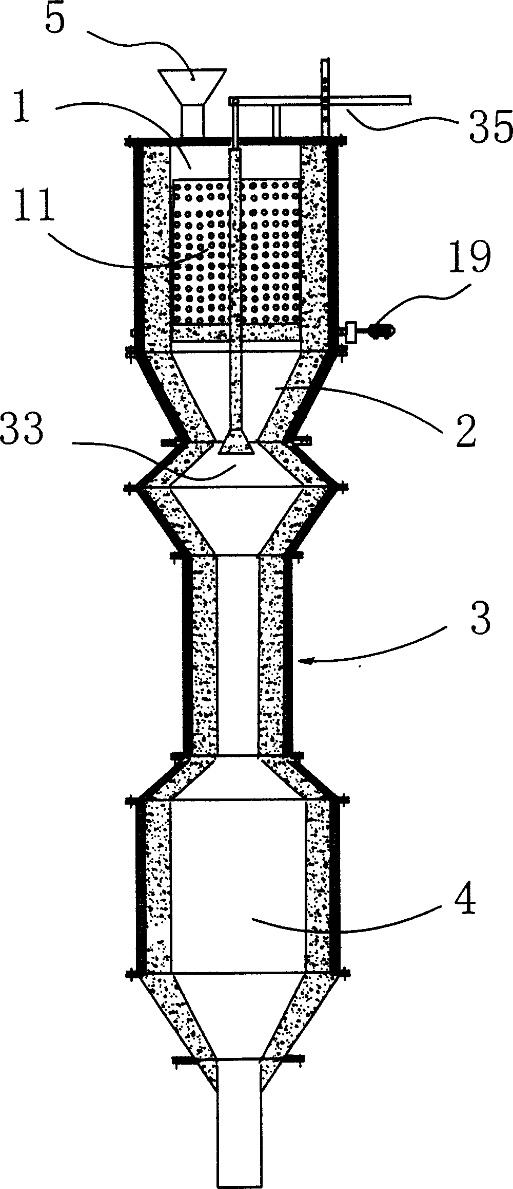
[0019] Figure 1, figure 2 and image 3 As shown: the preheating chamber 1 is in the shape of a square cylinder, with two inner grate plates 11 and two outer grate plates 12, the outer grate plates 12 are placed vertically, and the inner grate plates 11 are placed obliquely, forming two symmetrical spaces for storing materials 13, and a ventilation space 14 with a triangular cross-section is formed between the two inner grate plates 11, and the smoke outlet 15 is arranged on the side of the outer grate plate 12. Inside and outside grate plate 11,12 can be circular hole type grate plate, also can be slotted grate plate (fence shape grate plate), what this example adopted is the circular hole type grate plate. The hot gas coming up from the fluidized pre-calcination chamber 2 enters the ventilation space 14, then passes through the inner and outer grate plates 11, 12 and materials transversely, and is discharged through the smoke outlet 15, the ash collecting hopper 16 and the p...


PUM


Abstract

A calcining apparatus for high-granularity fluidized cement clinker is composed of the preheating chamber which is a moving bed, the fluidized pre-calcining chamber which is a reverselyconic internal circulating bed, the fluidized calcining chamber which is a vertical cylindrical fluidized bed, and the cooling chamber which is a vertical cylindrical moving bed. Its advantages are high ventilation uniformity, high thermal stability and high quality of clinker.

Description

technical field [0001] The invention relates to cement calcining equipment, in particular to a large particle fluidized cement clinker calcining device. Background technique [0002] Existing cement calcining equipment is mainly divided into two types: vertical kiln and rotary kiln. The materials in the rotary kiln are piled up, and the gas-solid heat exchange efficiency is low. The kiln cavity of the existing shaft kiln is a vertical cylinder, and preheating, calcination and cooling are all completed in the same chamber. During the calcination process, the material moves from top to bottom, so it is also called moving bed. Compared with the cement rotary kiln production line with large investment and low efficiency, the vertical cement kiln production line has the advantages of small investment, less land occupation, and lower technical requirements for equipment manufacturing and production management. There are more than 6,000 cement shaft kiln production lines in my co...

Claims


Application Information

Patent Timeline
Patent Type & Authority Patents(China)
IPC IPC(8): C04B7/43C04B7/44C04B7/45C04B7/47F27B1/04
Inventor 徐德龙肖国先丁松雄李晓光范海宏邓军平
Owner XI'AN UNIVERSITY OF ARCHITECTURE AND TECHNOLOGY
Why Eureka
Try Eureka