Check patentability & draft patents in minutes with Patsnap Eureka AI!

Direct-convertion receiver

A receiver and direct technology, applied in FM carrier systems, electrical components, transmission systems, etc., can solve problems such as distortion, direct conversion receiver bandwidth narrowing, and oscillation frequency offset

Inactive Publication Date: 2004-10-13
PANASONIC CORP
View PDF0 Cites 0 Cited by
  • Summary
  • Abstract
  • Description
  • Claims
  • Application Information

AI Technical Summary

Problems solved by technology

[0009] In a radio receiver, if in addition to receiving the radio waves required to be received, other radio waves that become interfering radio waves are captured by the receiving antenna at the same time, especially if multiple interfering waves are captured, the signal level is high enough for the receiving bandwidth. When the degree of influence occurs, there is a problem that distortion due to intermodulation will occur between these received radio wave signals and thus reduce the reception sensitivity of the radio wave (request signal) that is required to be received
[0012] If the low-pass cut-off frequency of the I low-pass filter and the Q low-pass filter is set lower, the bandwidth of the direct conversion receiver is narrowed so that the interference of radio waves (that is, adjacent radio waves) in adjacent channels is reduced The benefits of radio wave influence, but there will be such a problem, if the oscillation frequency of the local oscillator has been greatly shifted and separated from the carrier frequency of the received radio wave, resulting in the required received signal components in the I low-pass filter and Q low-pass outside the passband of the filter, then components of this requirement will be canceled and not demodulated

Method used


Image

  • Direct-convertion receiver
  • Direct-convertion receiver
  • Direct-convertion receiver

Examples


no. 1 example

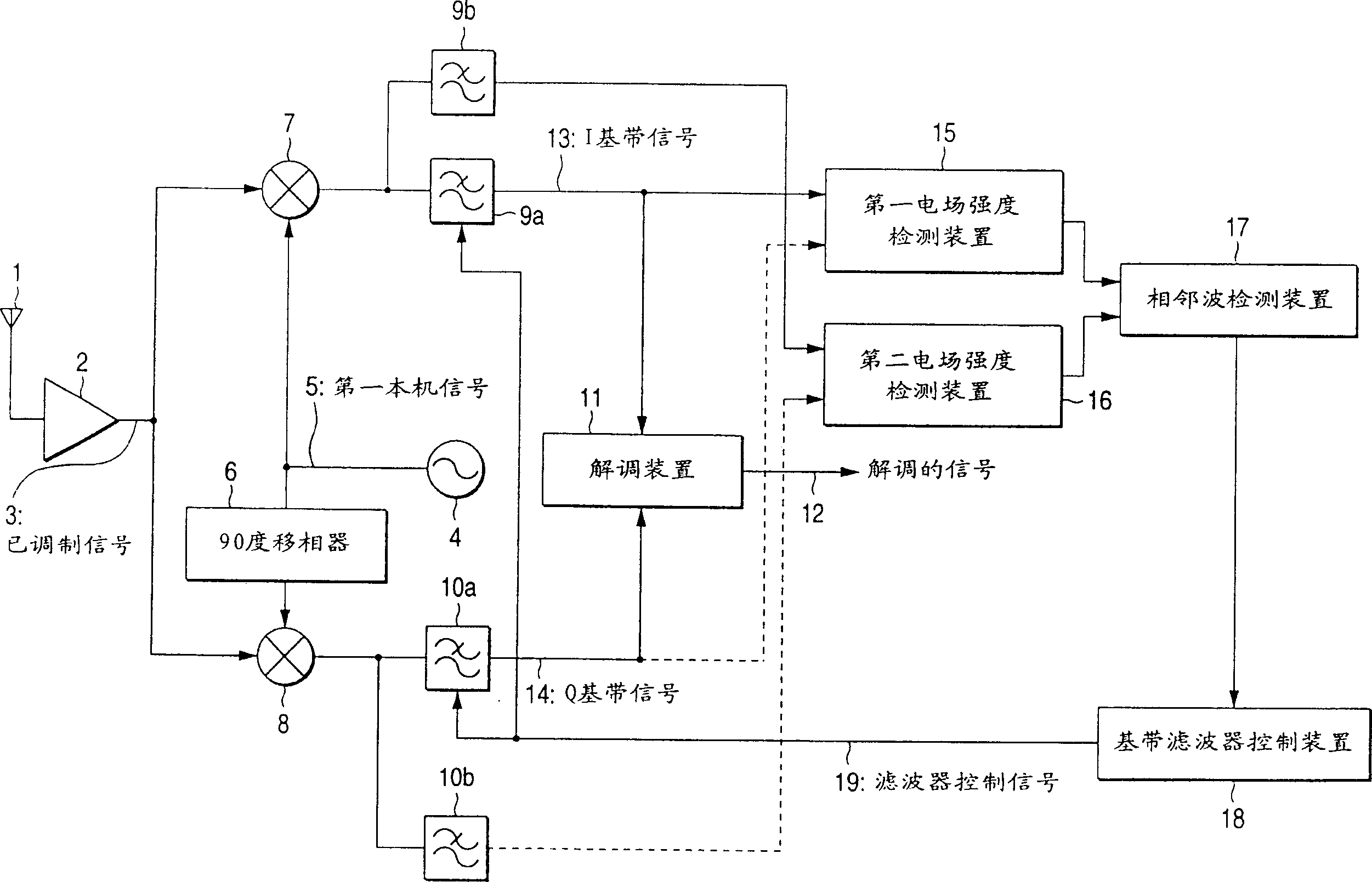
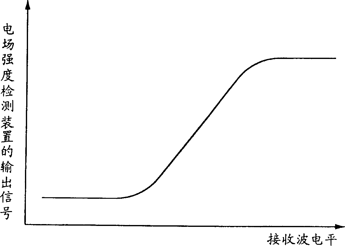
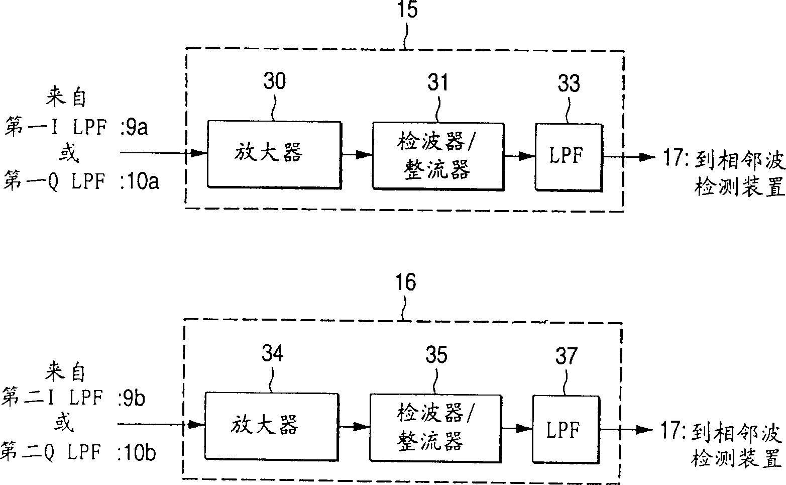
[0055] figure 1 is a block diagram showing the main configuration of the receiver circuit of the direct conversion receiver according to the first embodiment of the present invention. figure 2 is a view showing output characteristic curves of the first and second electric field intensity detecting means. image 3 is a block diagram showing a first example of the electric field intensity detecting device. Figure 4 is expressed in image 3 A view of the output waveform of the electric field strength detection device in the first example. Figure 5 is a block diagram representing a second example of the electric field strength detecting device; Figure 6 yes means Figure 5 The view of the output waveform in the electric field strength detecting device of the second example; Figure 7 is a block diagram showing the configuration of the adjacent radio wave detection device; Figure 8 is a block diagram representing a first example of baseband filter control means; Figur...

no. 2 example

[0102] Figure 14 is a block diagram showing the main configuration of a receiver circuit of a direct conversion receiver according to a second embodiment of the present invention. Figure 15 is a block diagram showing the arrangement of the electric field intensity maintaining means. Figure 16 is a block diagram showing the configuration of the baseband filter control device.

[0103] In the direct conversion receiver according to the second embodiment, instead of the figure 1 In the second electric field intensity detecting means in the first embodiment, an electric field intensity maintaining means 28 and a CPU 29 are provided. Therefore, the electric field strength maintaining means 28 and the baseband filter control means 18 are controlled by the CPU 29 . Since the configuration of other parts is basically similar to that of the first embodiment, only the different parts of the second embodiment will be explained here.

[0104] The first electric field strength dete...


PUM


Abstract

A directly translation receiver comprises a first electric field strength detecting means 15 and a second electric field strength detecting means 16, the signal levels of received signals are detected within a plurality of different frequency bands, then an adjacent wave detecting means 17 based on this output signal detect whether or not adjacent waves are contained, then a filter controlling signal 19 is output to a first I low-pass filter 9a and a first Q low-pass filter 10a from a baseband filter controlling means 18 according to whether or not the adjacent waves are contained, whereby low-frequency cut-off frequencies of the first I low-pass filter 9a and a first Q low-pass filter 10a are switched and controlled. Accordingly, a receiving sensitivity can be improved by reducing an influence of an adjacent wave and a tolerance for frequency offset of an oscillation frequency of a local oscillator relative to a carrier frequency of a received signal can be enhanced.

Description

technical field [0001] The present invention relates to a mobile communication device, such as a personal handyphone, a mobile phone, a pager, etc., and more particularly to a direct conversion receiver using a direct conversion system. Background technique [0002] In recent years, major radio communication systems used in mobile communication, such as personal portable telephones, mobile telephones, radio paging equipment (pagers), cordless telephones and the like have been remarkably spread. It is well known that, among the receiver systems of these radio communication systems, the configuration of the direct conversion receiver is easy to integrate, suitable for miniaturization and light in weight. [0003] A direct covering receiver is known in the prior art, for example a configuration in Unexamined Patent Publication Hei 7-135514. An example of a receiver circuit for a prior art direct conversion receiver is shown in Figure 17 . Figure 17 shows the configuration of...

Claims


Application Information

Patent Timeline
IPC IPC(8): H04L27/14H04B1/30
CPCH04B1/30
Inventor 片山浩
Owner PANASONIC CORP
Features
  • R&D
  • Intellectual Property
  • Life Sciences
  • Materials
  • Tech Scout
  • Unparalleled Data Quality
  • Higher Quality Content
  • 60% Fewer Hallucinations
Learn More