
Diffuser with dual-column blades arranged radially and serially

A diffuser and vane technology, which is applied in the field of radial tandem double-row vane diffusers, and can solve problems such as narrow flow cross-sections

Inactive Publication Date: 2004-10-20
孙敏超
View PDF0 Cites 4 Cited by
  • Summary
  • Abstract
  • Description
  • Claims
  • Application Information

AI Technical Summary

Problems solved by technology

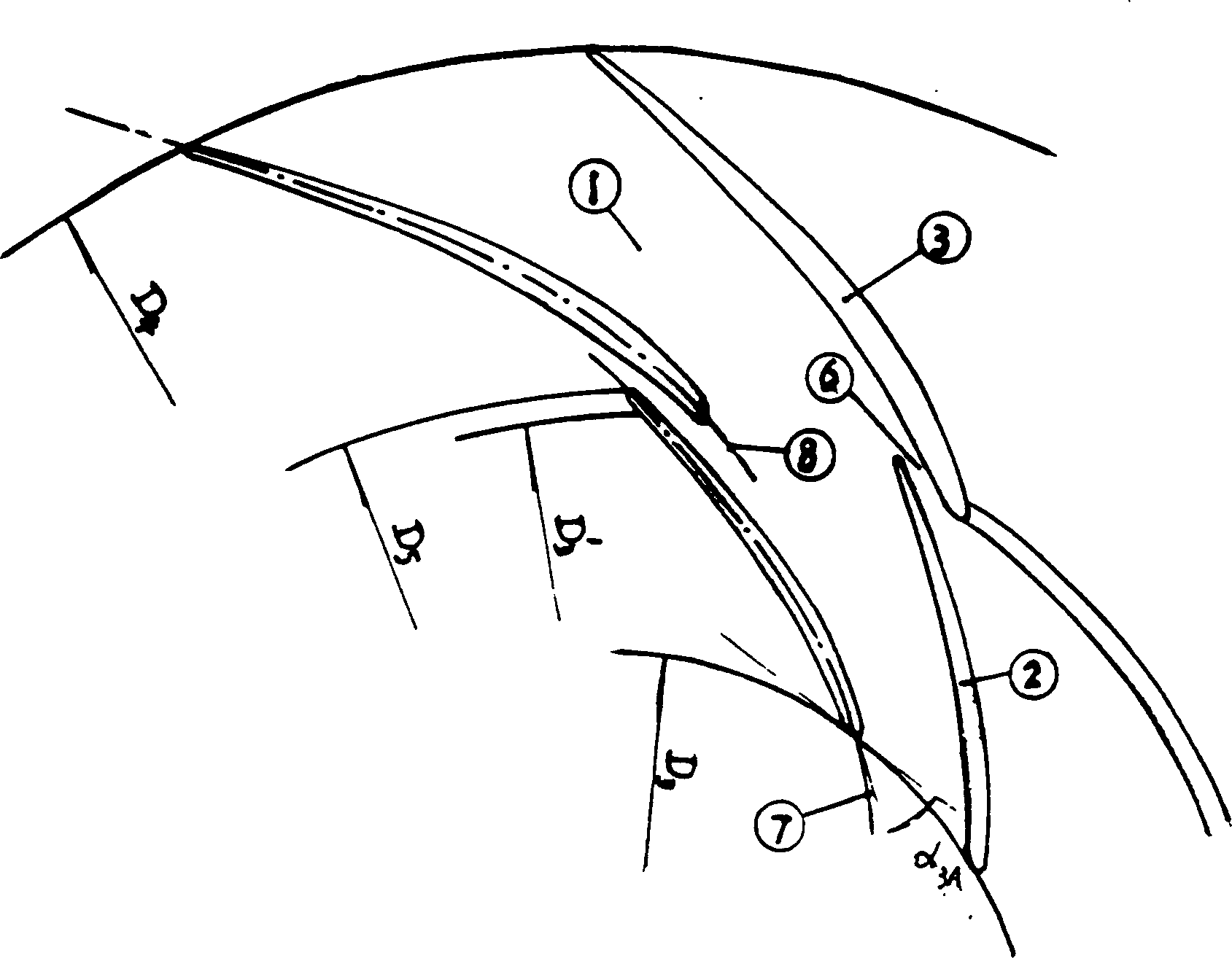
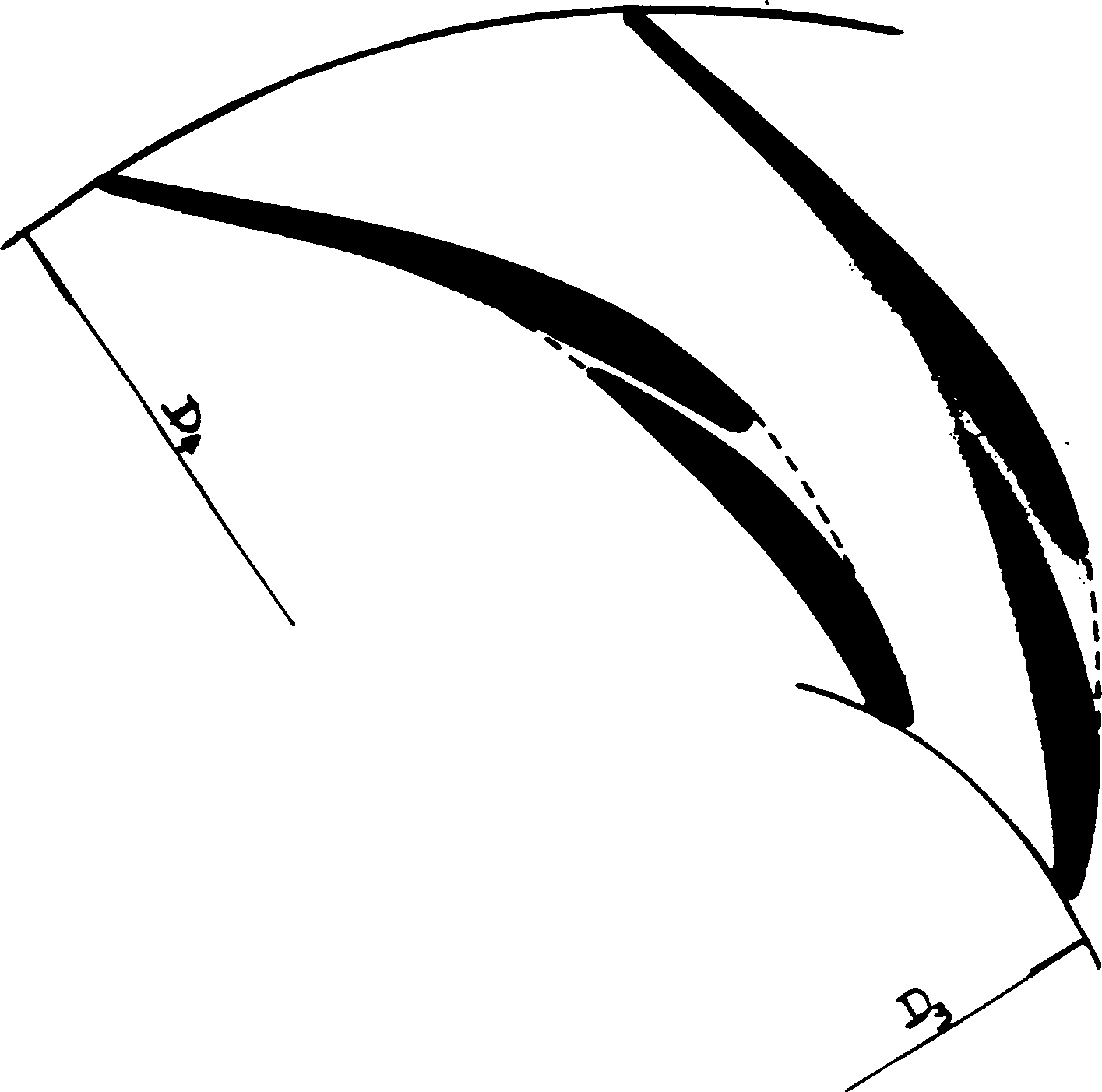
The limitations and defects of this structure are: the shape configuration of the radial series double-row vane diffuser, which can make the performance of the centrifugal compressor significantly improved compared with the single-row vane diffuser, is limited to the back surface of the outlet part of the front row of blades. The converging channel formed on the ventral surface of the inlet part of the rear row of blades is in a narrow state (the flow section of the channel is very narrow) ( figure 1 )

Method used


Image

  • Diffuser with dual-column blades arranged radially and serially
  • Diffuser with dual-column blades arranged radially and serially
  • Diffuser with dual-column blades arranged radially and serially

Examples


Embodiment Construction

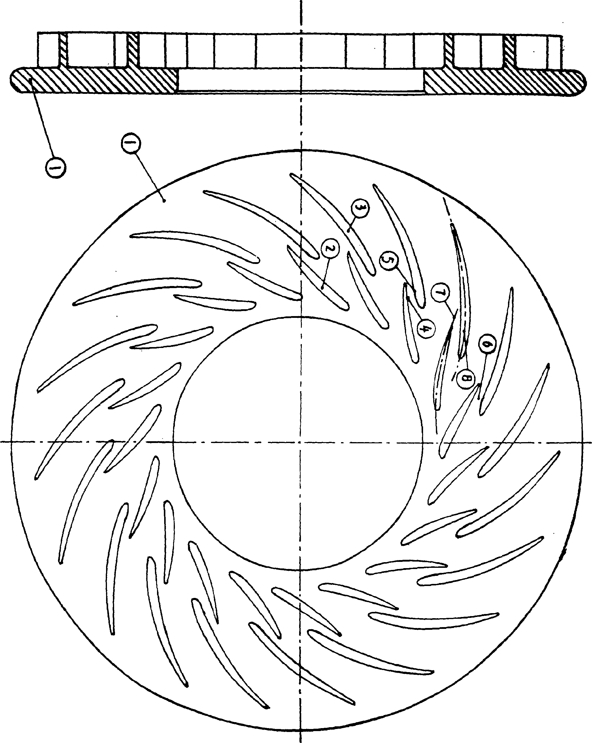
[0014] image 3 Schematic view of the structure of a radially serially arranged double-row vane diffuser constructed for the present invention. The radially arranged double-row vane diffuser is composed of three parts: an annular bottom plate ①, an annular cascade composed of vanes in the front row ②, and an annular cascade composed of blades in the rear row ③. The vanes of the front cascade ② and the rear cascade ③ are consolidated on the bottom plate ① (formed by integral precision casting or CNC milling). On the same side of the bottom plate ①, the front and rear rows of cascades ② and ③ are arranged radially in series with each other and staggered along the circumference (the diameter at the trailing edge of the blades of the front cascade ② can be greater than or equal to or smaller than that of the rear cascade ③ diameter of the blade inlet leading edge). The curved concave-convex direction of the middle arc ⑧ of the rear row of blades is the same as the curved concave...


PUM


Abstract

A diffuser for centrifugal air compressor has front and back rings of blades, which are serially arranged in a ring and are alternatively arranged between two rings. The curved directions for the blades in different rings are different. Its advantages are high efficiency and wide range of flow variation in enlarged high-efficiency region and stable working region.

Description

technical field [0001] The invention relates to a vane diffuser of centrifugal compressor technology, that is, a radially serially arranged double-row vane diffuser. Background technique [0002] The performance comparison test of the compressor equipped with a single-row vane diffuser and a radially arranged double-row vane diffuser shows that: the radially arranged double-row vane diffuser can pass through the different matching positions of the front and rear cascades. The combination of changes in mutual positional geometric parameters such as gaps and overlapping degrees and the appropriate selection of the shape and chord length ratio of the two rows of cascade blades can form different shapes of convergent channels, thereby effectively realizing the two rows of diffuser cascades. Controlling the flow around (controlling the flow separation and aerodynamic load distribution on the blade surface) significantly improves the performance of the centrifugal compressor, make...

Claims


Application Information

Patent Timeline
IPC IPC(8): F04D29/28F04D29/44
CPCF04D29/444F05D2250/52
Inventor 孙敏超
Owner 孙敏超
Learn More