Three-axis pivot structure

A three-axis, pivotal technology, applied in the direction of instruments, electrical digital data processing, calculation, etc., can solve the problems of unstable center of gravity, inconvenient operation, cost increase, etc., and achieve the effect of increasing convenience

Inactive Publication Date: 2004-11-03
MITAC INT CORP
View PDF0 Cites 0 Cited by
  • Summary
  • Abstract
  • Description
  • Claims
  • Application Information

AI Technical Summary

Problems solved by technology

[0008] However, the two-dimensional pivot structure 10 in the known technology can only provide rotation in two directions (as shown by the arrow) in use, because the two-dimensional pivot structure 10 is mainly used to support the LCD panel 3 of the computer, If a pivot structure that rotates around the third axis of rotation 160 (vertical direction) can be added, the practicability will be greatly improved, because the current two-dimensional pivot structure 10 cannot provide the rotation of the LCD panel 3 to the third axis of rotation 160 function, so the user can only rotate the LCD panel 3 together with the bracket 2, so it is quite inconvenient to operate
[0009] In addition, because the size of the LCD panel 3 supported by the two-dimensional pivot structure in the known technology is relatively large, and it is not supported on the center of gravity of the LCD panel 3, poor support positioning or rotation often occurs during long-term rotation. When the center of gravity is unstable, there are usually three solutions in the known technology: the first is to increase the locking force of the nut 121, the second is to increase the number of elastic washers 122 or expand the size of the elastic washers 122, and the third is to Use the second pivot 14 of a larger size model; the first is to increase the frictional resistance of rotation by increasing the positive force between the elastic washers 122, and the second is to expand the contact area between the elastic washers 122 One way is to improve the effective friction area of ​​the component assembly (equal to improve the coefficient of static friction), and the third is to increase the cross-sectional area of ​​the second pivot 14 so that it can be supported on the center of gravity of the LCD panel 3, but these three solutions Simultaneously also produce the shortcoming that is not easy to rotate and the problem that cost increases, and the locking force that increases nut 121 is only temporary maintenance measure, non-permanent solution, and increase the number of elastic gasket 122 or expand the elastic gasket 122 The size solution also involves the installation space of the two-dimensional pivot structure 10 and the change of the overall shape of the device. Obviously, this is not an ideal design solution.

Method used


Image

  • Three-axis pivot structure
  • Three-axis pivot structure
  • Three-axis pivot structure

Examples


Embodiment Construction

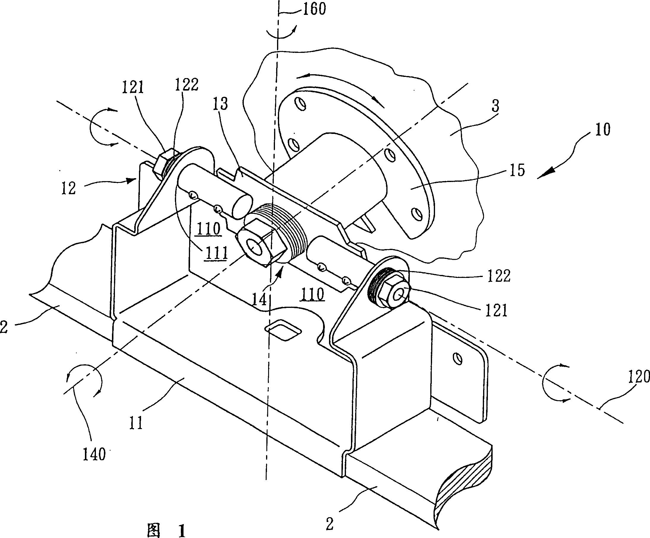
[0022] The three-axis pivot structure of the present invention is applied to an LCD panel combined with a computer or other objects, and the LCD panel is fixed on a base, using the three rotation directions provided by the three-axis pivot structure , so that the three-way rotation is performed between the LCD panel and the base, and the pivot structure can also be supported on the center of gravity of the LCD panel, so it has the functions of reducing shaking and increasing stability.

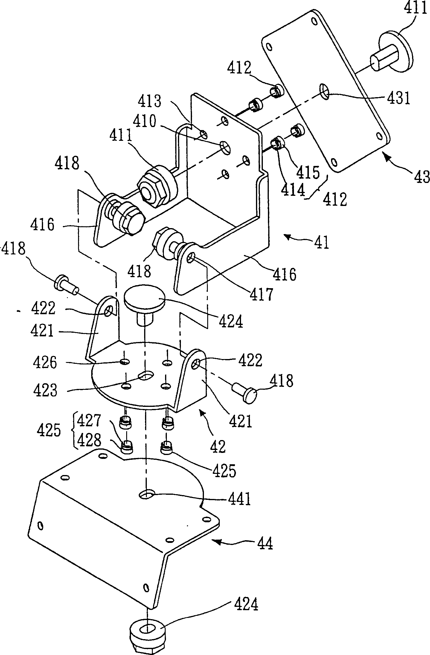
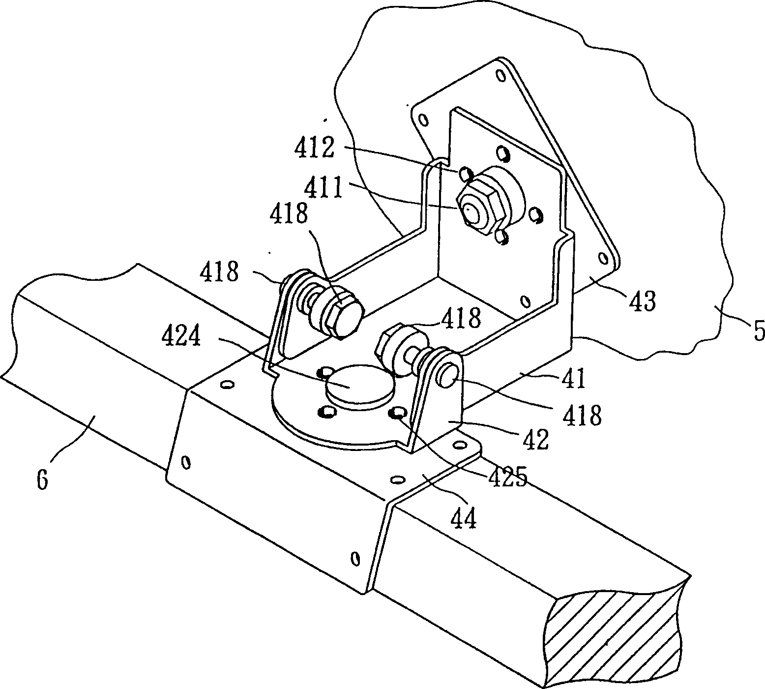
[0023] refer to figure 2 , The triaxial pivot structure 4 of the present invention includes an upper connecting plate 41 , a lower connecting plate 42 , an upper rotating plate 43 and a lower rotating plate 44 .

[0024] The upper connecting plate 41 is provided with a shaft hole 410 in the middle of its plate surface, and a first pivot 411 is combined on the shaft hole 410. The first pivot 411 is perpendicular to the upper connecting plate 41, and the upper connecting plate 41 is in the shaft...


PUM


Abstract

A three-axial pivot structure is composed of upper and lower joint plates and upper and lower rotary plates. Said upper joint plate has the first pivot perpendicular to it, the second pivot parallel to it and several slide friction elements around the first pivot. Said lower joint plate linked to the second pivot has the third pivot perpendicular to it and several slide friction elements around the third pivot. Said upper and lower rotary plates can be rotary relatively to said joint plates and in contact with relative slide friction elements.

Description

technical field [0001] The invention relates to a three-axis pivot structure, in particular to a pivot structure applied to a computer LCD panel and having the functions of three-axis rotation and fretting prevention. Background technique [0002] Press, usually have the pivotal structure of firmer function (such as being applied on computer LCD panel or similar device) generally be the pivotal structure of one-dimensional or two-dimensional form, can make LCD panel or similar device can have following The pivot position is the center of rotation, allowing limited degrees of freedom of rotation in both the front-to-back and left-to-right directions. [0003] As shown in Figure 1, it is a three-dimensional schematic diagram of a two-dimensional (two-axis) pivot structure 10 in the known technology, and the two-dimensional pivot structure 10 has a bottom plate 11, a first pivot 12, a rotating shaft plate 13. A second pivot 14 and an output shaft 15. Wherein, the bottom plate...

Claims


Application Information

Patent Timeline
IPC IPC(8): B25H1/06F16M11/12G06F1/16
Inventor 陈古峰
Owner MITAC INT CORP
Why Eureka
Try Eureka