Ring hoop hold-down device for drum pedal

A hoop, pedal technology, applied in the direction of instruments, percussion instruments, music auxiliary equipment, etc., can solve problems such as inability to firmly clamp, poor, design limitations, etc.

Inactive Publication Date: 2004-12-08
HOSHINO GAKKI COMPANY LIMITED
View PDF0 Cites 0 Cited by
  • Summary
  • Abstract
  • Description
  • Claims
  • Application Information

AI Technical Summary

Problems solved by technology

Therefore, when adjusting the hoop to press the device, one must reach out to the narrow space directly below the pedal 111 to operate the adjusting bolt 125 in a state of manual search, which is not only troublesome but

Method used


Image

  • Ring hoop hold-down device for drum pedal
  • Ring hoop hold-down device for drum pedal
  • Ring hoop hold-down device for drum pedal

Examples


Embodiment Construction

[0044] Hereinafter, the present invention will be described in detail with reference to the drawings.

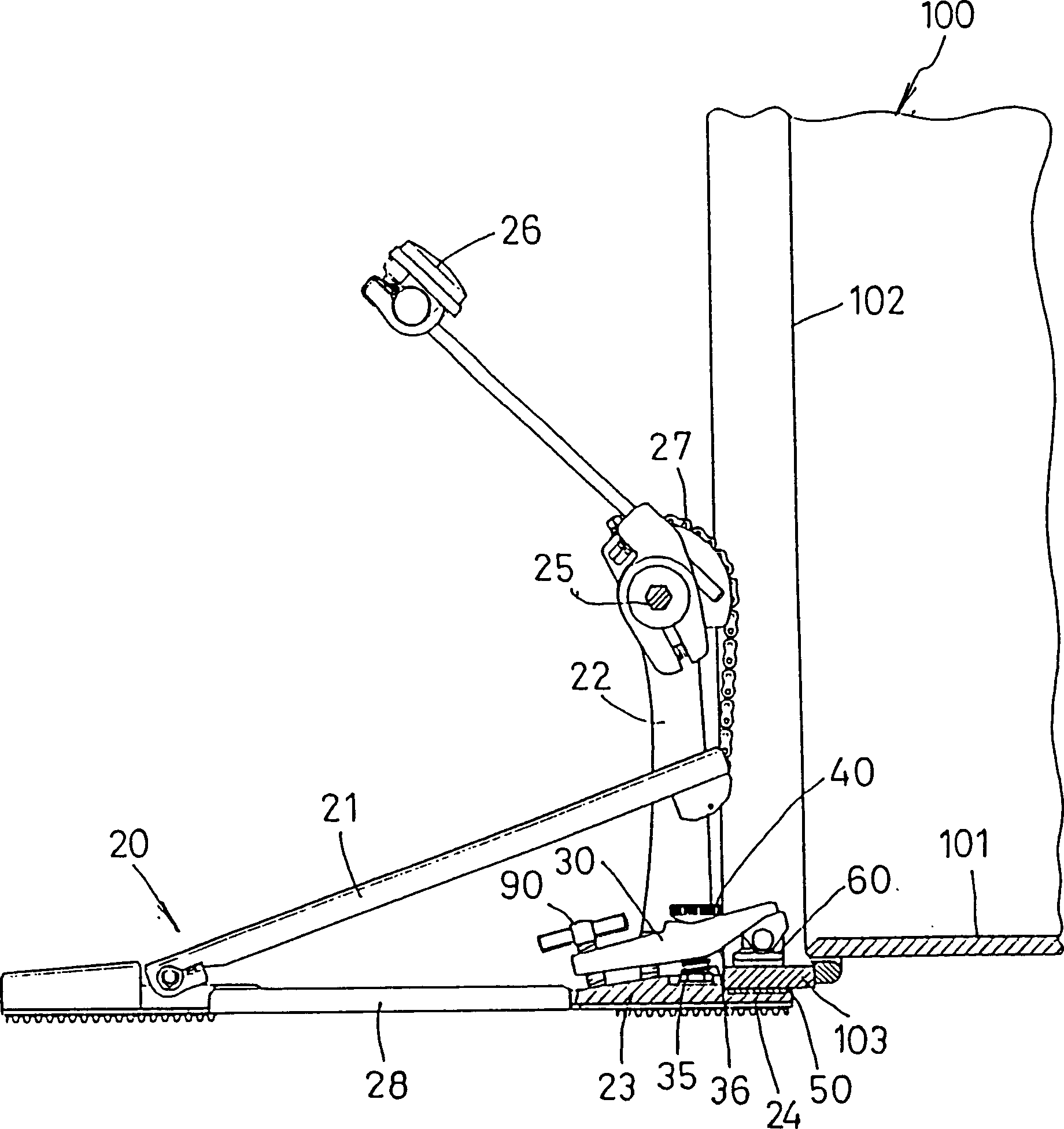
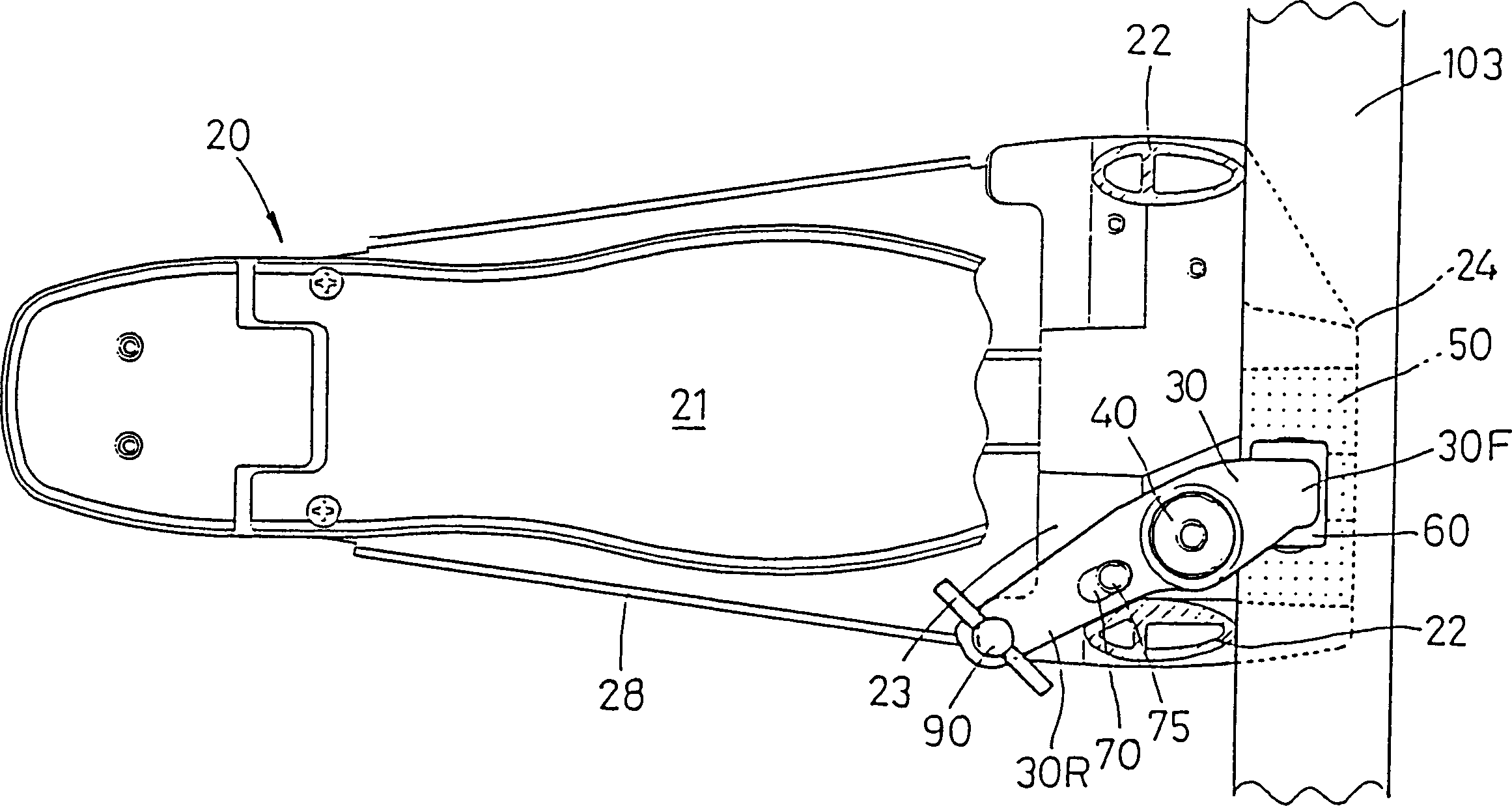
[0045] figure 1 The bass drum 100 shown has the same Figure 13 The description of the same structure, and the label 101 is a drum shell, 102 is a drum head, and 103 is a drum hoop. In addition, the illustrated drum pedal device 20 itself is also known in the past, and the label 21 is a drum pedal, 22 is a pillar, 23 is a pillar base on which the above-mentioned pillar 22 is erected, and 24 is a hoop at the front of the above-mentioned pillar base 23. Receiving part, 25 is the rotary shaft straddling the above-mentioned pillar 23, 26 is the beater installed on the above-mentioned rotary shaft 25, and 27 is a chain member that utilizes the pedal 21 to move the rotary shaft 25 up and down.

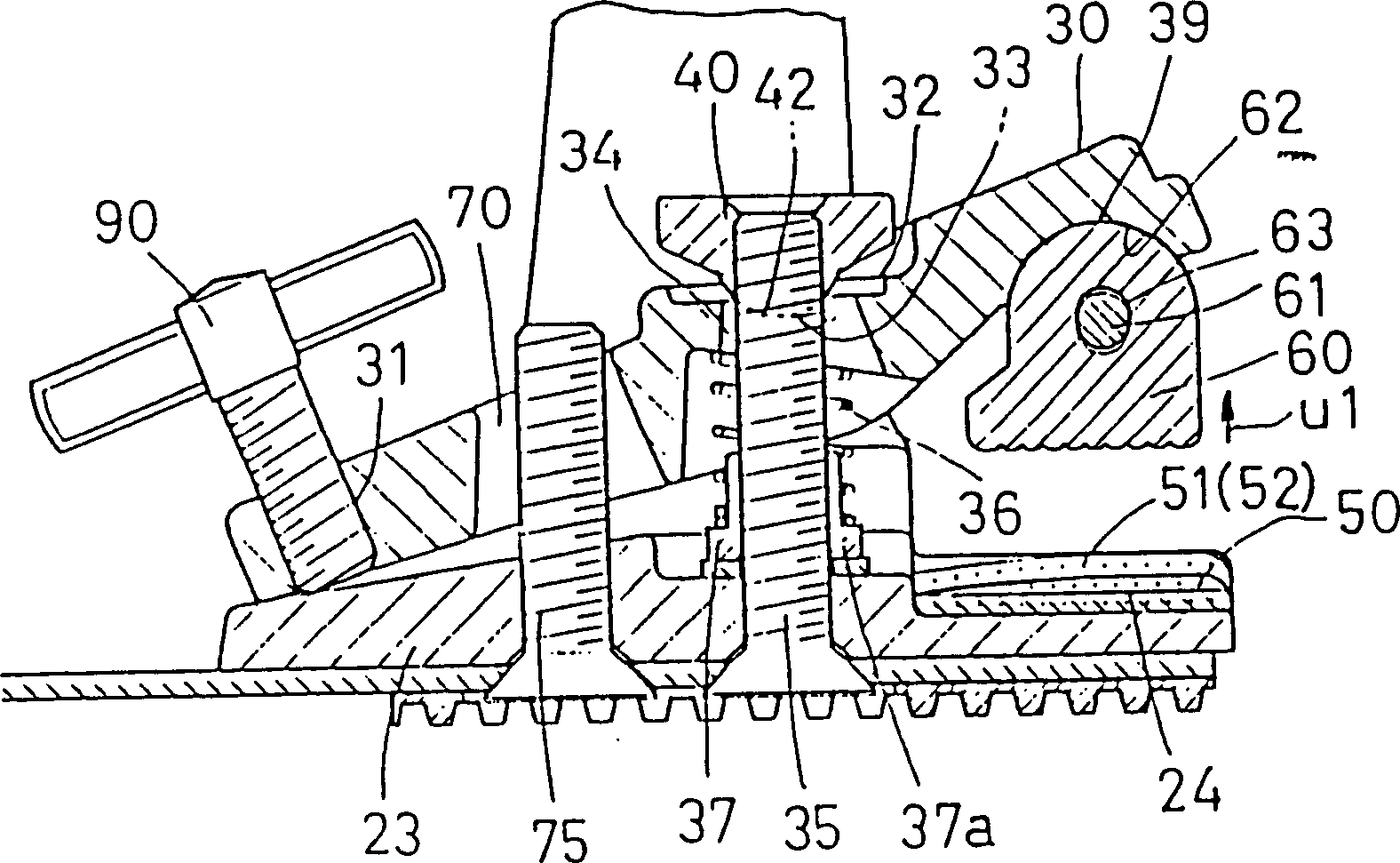
[0046] The hooping device of the present invention, as shown in the accompanying drawings, is provided between the front part of the hoop clip body 30 supported on the pillar base 23 of...


PUM


Abstract

The invention provides the device with good operability which can clamp the drum hoop surely irrelevantly to its thickness and eliminates the need to make a clamping bolt long. A hoop clamp main body has a pedestal part having a recessed curved surface part in the front-rear direction and a through hold hole penetrating the seat part a support bolt penetrating the through hold hole is stood on a column base, and a spring member which always energizes the seat part upward is interposed between the reverse surface side of the seat part and the column base; and the height of the hoop clamp main body as to the support bolt is adjusted in a free angle state in the front-rear direction of the hoop clamp main body with an adjusting nut which threadably engages the support bolt stood penetrating the through hold hole and is fitted in the recessed curved surface part of the seat part energized by the spring member.

Description

technical field [0001] The invention relates to a hoop pressing device for a drum pedal. Background technique [0002] The hoop of the previous bass drum pedal presses the device, an example of which is as Figure 13 to Figure 15 shown. This kind of hoop pressing device is the structure disclosed by the applicant in the Publication No. Hei 4-96794, and the hoop supported on the pillar base 113 of the drum pedal 110 in the forward and backward direction via the shaft 121. Between the front part of the clamp body 120 and the hoop receiving part 114 at the front part of the above-mentioned pillar base 113, there is a pressing jaw 122 that presses the drum hoop 103, and a jaw 122 that is screwed to the hoop clamp body is provided at its rear. Through the screw part 126 (refer to Figure 14 ) to fix the clamping bolt 125 on the hoop clip body 120. Such as Figure 14 and Figure 15 As shown, the pressing jaw 122 is rotatably held by the shaft 123 in the front-rear direction. ...

Claims


Application Information

Patent Timeline
IPC IPC(8): G10D13/02G10G5/00
Inventor 星野义裕
Owner HOSHINO GAKKI COMPANY LIMITED
Why Eureka
Try Eureka