

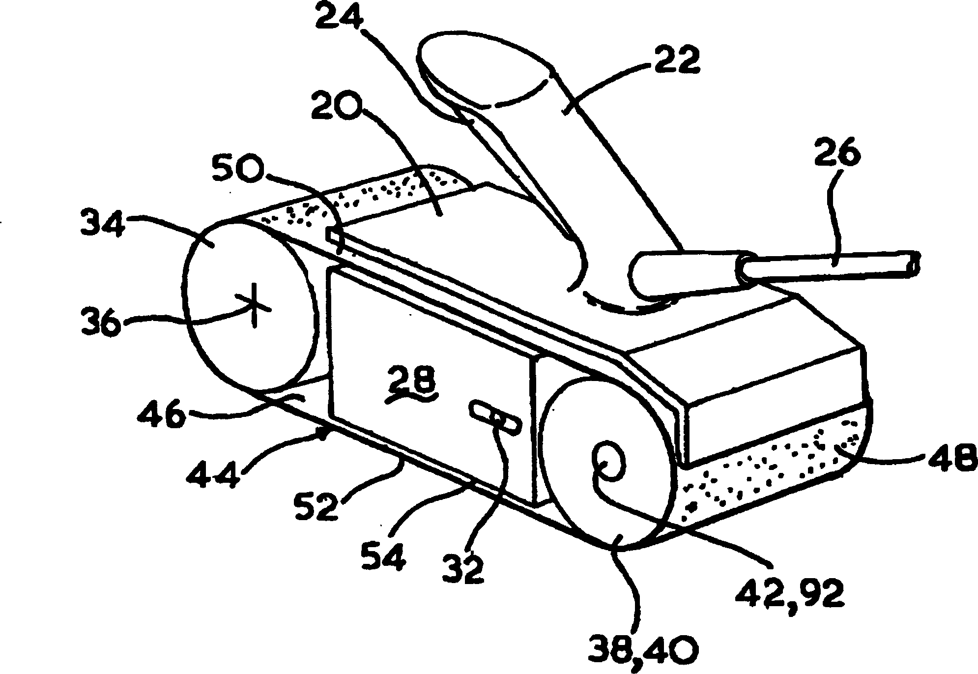
Belt polishing machine
A technology of grinding machine and electric motor, which is applied in the direction of portable grinding bed, grinding/polishing equipment, grinding machine, etc., which can solve problems such as limitations and achieve a wide range of effects
- Summary
- Abstract
- Description
- Claims
- Application Information
AI Technical Summary
Problems solved by technology
Method used
Image

Examples
Embodiment Construction
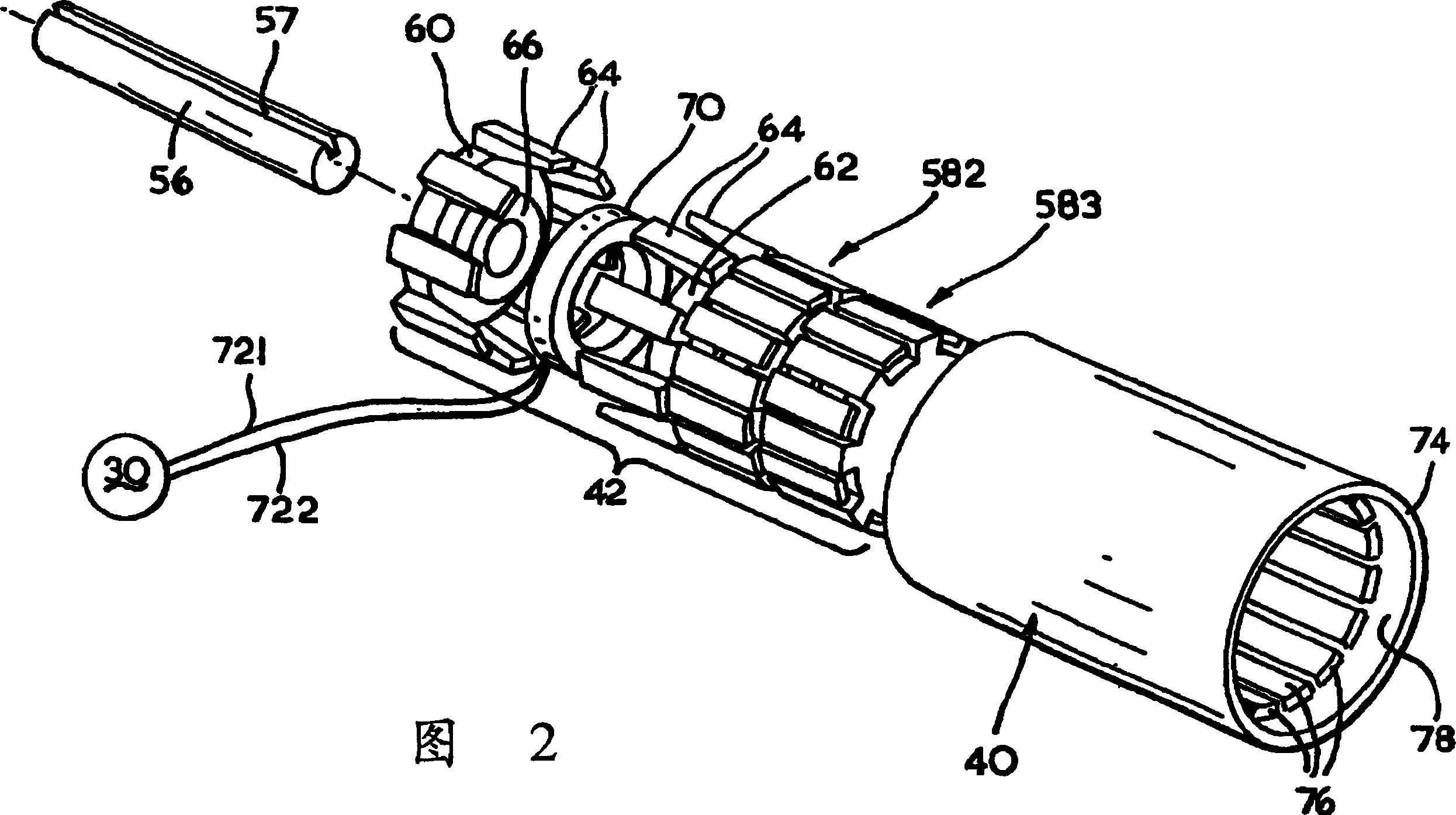
[0039] With reference to the accompanying drawings in particular figure 1 As shown, the belt sander includes a body part (20) having a handle (22), an electric trigger switch (24) located on said handle (22), and a rear end of the handle (22) into the body The input cable (26) in the part (20) and capable of transmitting current is connected to the main part (20) and includes a housing (28) with a power module (30) and a tension adjuster (32) of the belt, The driven roller (34) rotatably arranged on the shaft (36), the shaft mounted on the tensioner side of the belt, the driving roller (38) formed by the drum of the rotor of the motor, is rotated by the rotor The outer drum (40) surrounds the motor's stator (42), which is connected to the main body part (20) as is the shaft (36) connected to the belt tensioner (32) on the same side of the same side; the sandpaper belt (44) surrounding and supported by the driving roller (38) and the driven roller (34), wherein the housing (28...
PUM
 Abstract
Description
Claims
Application Information