Tap converter

A conversion device and tap changer technology, applied in the direction of transformers, electrical components, variable inductors, etc., can solve the problems such as the limitation of the width and size of the transformer box, the deformation of the transformer box, and the assembly and adjustment taking a long time.

Inactive Publication Date: 2005-01-05
MITSUBISHI ELECTRIC CORP
View PDF0 Cites 1 Cited by
  • Summary
  • Abstract
  • Description
  • Claims
  • Application Information

AI Technical Summary

Problems solved by technology

[0024] (1) Among the structural elements in the tap changing device, since the operating mechanism 3, the first direction changing device 42, and the oil reservoir 5 are installed on the wall surface and the top plate of the transformer box 1 through respective mounting parts, Therefore, it is difficult to ensure the dimensional accuracy between the connecting elements including the connecting shaft and the oil pipeline, and its assembly and adjustment take a long time;
[0025] (2) In addition, since the transformer box 1 is a thin-plate container, deformation of the transformer box is likely to occur. Once assembled, the installation positions of the operation box 3, the first direction changing device 42, the tap changer 2 and the oil reservoir 5 It is easy to produce shape errors such as parallelism, so the fitting part of the connecting shaft will be unstable, and oil leakage will occur from the fastening part of the oil pipeline;
[0027] (4) In addition, although there is no special problem in the case of a high-voltage, high-capacity transformer with a large size of the transformer box 1, for a low-voltage, small-capacity transformer with a small size of the transformer box 1, the width dimension of the transformer box Due to the limitation, the installation space of the mounting part B10 of the first direction changing device 42 and the mounting part C11 of the oil reservoir 5 cannot be ensured;
[0028] (5) In addition, since the second direction changing device 21d is mounted on the head cover 21c of the tap changer 2, when the tap changer is maintained and inspected, when the head cover 21c is opened, Disassemble the transverse connecting shaft 43, thereby deteriorating the workability during maintenance and inspection;
[0029] (6) In addition, since the transformer body box and the tap changer box are integrated, the tap changer can only be assembled after the assembly of the transformer body is completed, and the total assembly time of the transformer cannot be shortened.

Method used


Image

  • Tap converter
  • Tap converter
  • Tap converter

Examples


Embodiment Construction

[0041] Embodiment 1

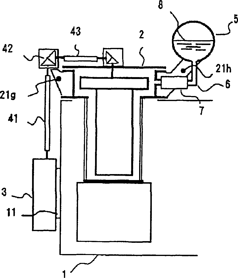
[0042] figure 1 It is a cross-sectional view showing a tap changing device according to Embodiment 1 of the present invention. figure 1 Here, the description of the same symbols as in the conventional example is omitted. 21g is the attachment B of the present embodiment that supports the first direction changing device provided on the head housing 21a of the tap changer 2. 21h is the attachment C of the present embodiment that supports the oil reservoir 5 provided on the head housing 21a of the tap changer 2.

[0043]The operation of the tap changing device configured as described above is the same as the aforementioned conventional example, but the assembly sequence of the structural elements of the tap changing device is different as described below.

[0044] (1) First, prepare in advance the transformer box 1 in the state where the mounting member A of 9 is fixed at a predetermined position of the transformer box 1 by, for example, welding;

[0045] (2)...


PUM


Abstract

To provide a tap changing device which can shorten the assembling time of the device itself and a transformer and can stably obtain a driving force even when many or few errors occur in the attaching positions of an operating mechanism, a tap changer, and a conservator and in which the direction changing device and conservator of the device can be attached to the transformer almost effortless even when the size of the transformer is relatively small and no oil leakage occurs from an oil pipeline. The first direction changing device 42 and conservator 5 of this tap changing device are attached to the head case 21a of the tap changer respectively through fittings 21g and 21h installed to the case 21a.

Description

Technical field [0001] The present invention relates to a tap changer used in electrical equipment such as a power transformer, and more particularly to an installation structure of structural elements constituting the tap changer. Background technique [0002] Generally, the tap changer device mainly includes: a tap changer mounted on the top plate of the transformer box in a suspended state; a driving force for rotating a specific part of the tap changer is generated and installed on the side wall of the transformer box closer to the ground. Operating mechanism; a transmission mechanism composed of a connecting shaft used to transmit the driving force to the tap changer and a direction change device for changing the direction; filling the oil tank of the tap changer with insulating oil to absorb temperature changes The oil storage device that produces the expansion and contraction of the insulating oil; the oil pipeline connecting the head of the tap changer and the oil storage...

Claims


Application Information

Patent Timeline
Patent Type & Authority Patents(China)
IPC IPC(8): H01F27/14H01F27/02H01F29/02H01F29/04
Inventor 吉田和夫三原有次
Owner MITSUBISHI ELECTRIC CORP
Why Eureka
Try Eureka