
Method and device for acquisition of voltage and current magnitude of radio frequency power wave applied to radio frequency load

A technology of radio frequency power and voltage value, applied in the direction of measuring devices, circuits, discharge tubes, etc., can solve the problems of unknown calibration algorithm of voltage/current probes, serious temperature drift, etc.

Inactive Publication Date: 2005-02-02
MKS INSTR INC
View PDF2 Cites 2 Cited by
  • Summary
  • Abstract
  • Description
  • Claims
  • Application Information

AI Technical Summary

Problems solved by technology

Diode detectors are inherently non-linear for low signal levels and suffer from significant temperature drift
Unfortunately, the prior art has not been able to compensate for this, and the calibration algorithm for voltage / current probes is also unknown in the prior art

Method used


Image

  • Method and device for acquisition of voltage and current magnitude of radio frequency power wave applied to radio frequency load
  • Method and device for acquisition of voltage and current magnitude of radio frequency power wave applied to radio frequency load
  • Method and device for acquisition of voltage and current magnitude of radio frequency power wave applied to radio frequency load

Examples


Embodiment Construction

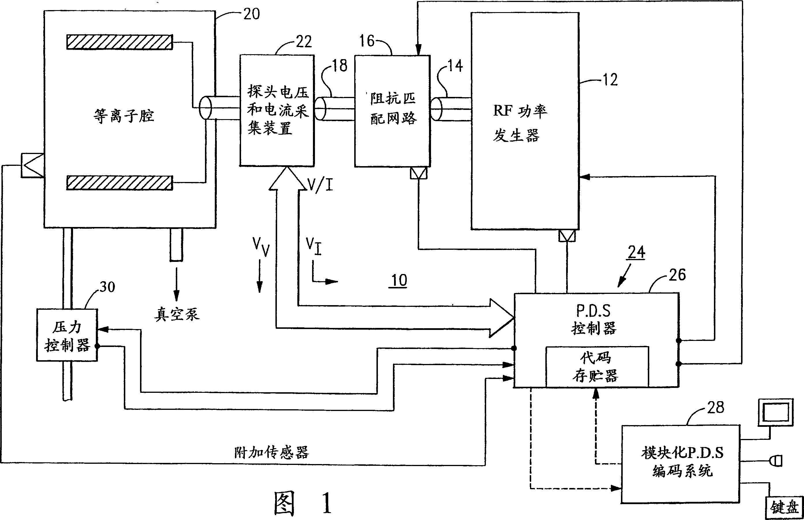
[0048] Referring to the accompanying drawings, first accompanying drawing 1, a plasma processing apparatus 10, such as for etching silicon wafers or other workpieces, it has an RF power generator 12, it generates a predetermined frequency, such as 13.56MHz, predetermined power level, such as a kilowatts of RF power. The RF power generator 12 supplies RF power to an impedance matching network 16 along conduit 14 . The output of impedance matching network 16 is coupled to the input of plasma chamber 20 by a power conduit. A probe voltage and current acquisition device 22 collects and represents the RF voltage V when the RF power is input into the plasma chamber 20 RF Voltage sampling value V V and also collects the RF current I representing the applied RF power RF Current sampling value V I . The plasma chamber 20 has a vacuum line connected to a vacuum pump, not shown, and a gas inlet through which an inert gas, such as argon, is introduced into the chamber. The voltage a...


PUM


Abstract

A technique for measuring the current, voltage and phase of an RF power wave to an RF load, accounts for the finite length of the voltage and current pickups, and corrects for effects of standing wave components of voltage and current. Voltage and current are computed as complex functions of the voltage pickup signal and the current pickup signal, based on coefficients precalibrated for said-predetermined radio frequency. Alternatively, a corrected current value can base on the corrected voltage value and complex load impedance.

Description

technical field [0001] This invention relates to the accurate measurement of the voltage, current and phase of RF power applied to a non-linear load, and more particularly to a method for measuring the current, voltage and phase of radio frequency (RF) electrical power supplied to an RF plasma chamber. The probe that makes the measurement. Background technique [0002] In a typical RF plasma generator arrangement, RF waves are generated at a predetermined frequency, ie, 13.56 MHz, by a high power RF source and transmitted along a power channel to a plasma chamber. Since there is usually a severe impedance mismatch between the RF power source and the plasma chamber, an impedance matching network is inserted between the two. Due to nonlinearities in the plasma chamber, and losses in the wires or in the impedance matching network, not all of the output power of the RF power generator reaches the plasma chamber. Therefore, it is more convenient to set a probe at the power inpu...

Claims


Application Information

Patent Timeline
IPC IPC(8): H01J37/32
CPCH01J37/3299H01J37/32082H01J37/32935G01R1/00
Inventor K·S·格里斯
Owner MKS INSTR INC
Learn More