
Rivetting die for bearing

A riveting and bearing technology, which is applied to bearing components, shafts and bearings, mechanical equipment, etc., can solve problems such as short service life, scratches on parts, and misalignment of two pieces of bearings

Inactive Publication Date: 2005-02-16
周新益
View PDF0 Cites 1 Cited by
  • Summary
  • Abstract
  • Description
  • Claims
  • Application Information

AI Technical Summary

Problems solved by technology

With this kind of mold, although the riveting of the bearing can also be realized, because the punch driven by the upper mold hits the rivet quickly at one time, it is easy to cause misalignment between the two bearing cages, and the gap between the steel ball and the pocket of the cage and the steel ball. The impact and shock generated by the ball and the ferrule channel will also cause the abrasion of these parts
As a result, the bearing will generate noise when it is in use
Therefore, the bearings produced using this mold are of poor quality and have a short service life

Method used


Image

  • Rivetting die for bearing
  • Rivetting die for bearing

Examples


Embodiment Construction

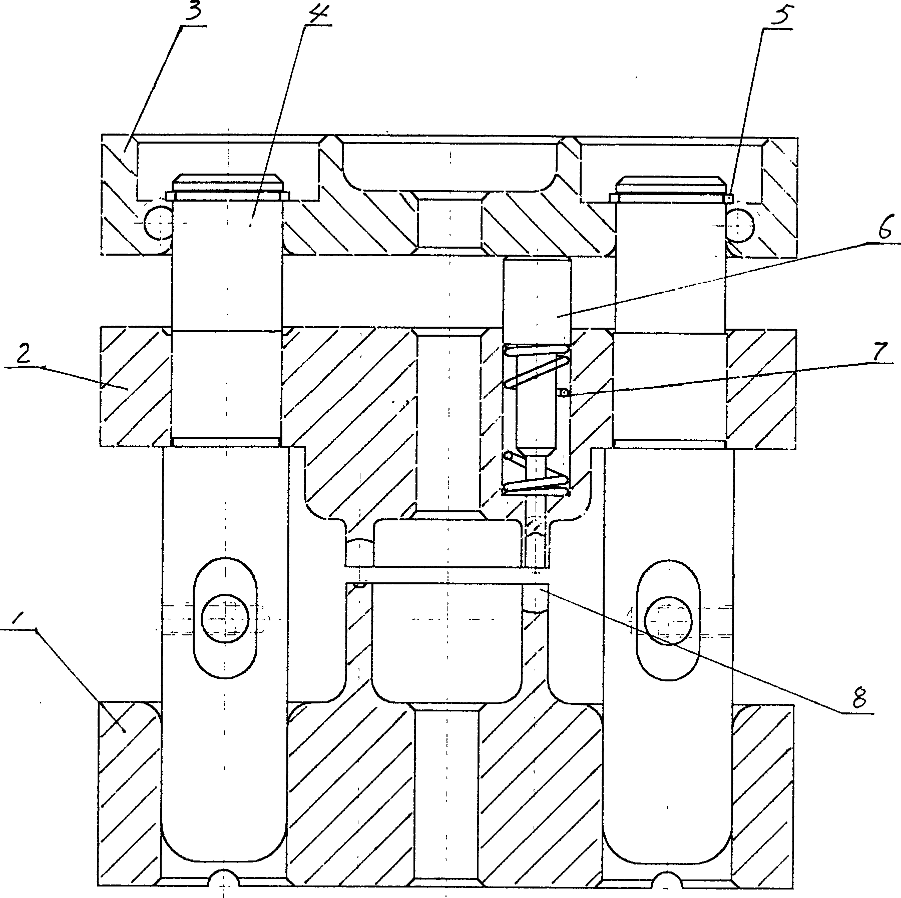
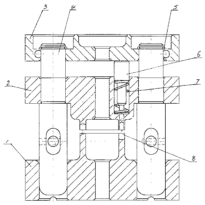
[0010] As shown in the drawings, the bearing riveting die of the present invention includes an upper die 2 and a lower die 1 . The middle of the lower surface of the upper mold 2 and the middle of the upper surface of the lower mold 1 are correspondingly processed with an annular boss 8, and the ends of the annular boss are circumferentially equidistant and correspondingly processed with arc-shaped notches to form a wave-shaped mold. The cavity is used for placing the bearing cage during riveting operation. Both sides of the annular boss 8 on the upper and lower dies 2 and 1 are correspondingly processed with through holes, and guide posts 4 are fixed in the two through holes on the upper die 2 . The lower end of the guide post 4 is inserted into the two through holes of the lower die 1 and can slide up and down in the through holes of the lower die 1 . A pressing plate 3 is arranged on the upper mold 2, and two through holes are also processed on the pressing plate 3, and th...


PUM


Abstract

A die for riveted assembling of steel balls into bearing cage is composed of upper and lower dies with ring bosses having wave-shaped cavity between corresponding surfaces the upper and lower dies have correspondingly through holes. A guide rod in the through hole of upper die can be inserted in the one on lower die in slide mode. There is a press plate above the upper die and a through hole on the press plate, the said through hole on the press plate, the said through hole is corresponding to through holes on upper and lower dies. The upper die has a ring of blind holes on its top surface and the ring boss on the bottom surface of upper die has through holes relative to said blind hole. Each blind hole and each through hole has a punch head in it. The bearing riveted-assembled by the said die features high quality and long service life.

Description

technical field [0001] The invention relates to a mold. Specifically, it is a bearing riveting die for riveting steel balls in a bearing cage. Background technique [0002] In the bearing processing industry, in order to rivet the steel balls in the cage, the common method is to use a punching machine to perform a one-time rapid impact on the upper mold of the mold to achieve stamping and shaping. Wherein, the mold used mainly consists of an upper mold, a lower mold and a guide post. During the riveting operation, the punch directly hits the upper die, and then the upper die drives the punch to quickly hit the rivet. With this kind of mold, although the riveting of the bearing can also be realized, because the punch driven by the upper mold hits the rivet quickly at one time, it is easy to cause misalignment between the two bearing cages, and the gap between the steel ball and the pocket of the cage and the steel ball. The impact and shock generated by the ball and the fe...

Claims


Application Information

Patent Timeline
IPC IPC(8): B21J15/10F16C43/06
Inventor 周新益张澄明华平
Owner 周新益
Learn More