
Waveguide array interferometer

An arrayed waveguide and arrayed optical waveguide technology, applied in the field of waveguides

Inactive Publication Date: 2005-03-02
李志扬
View PDF0 Cites 0 Cited by
  • Summary
  • Abstract
  • Description
  • Claims
  • Application Information

AI Technical Summary

Problems solved by technology

The fiber Bragg grating periodically modulates the refractive index along the fiber axis to generate Bragg reflection. It is a narrow-band notch filter or narrow-band reflector. It has a modular structure. It only needs to add a channel. Adding an additional fiber Bragg grating, but modulating the refractive index requires a special process during manufacture

Method used


Image

  • Waveguide array interferometer
  • Waveguide array interferometer
  • Waveguide array interferometer

Examples


Embodiment Construction

[0010] Below in conjunction with accompanying drawing and embodiment the present invention is described in further detail:

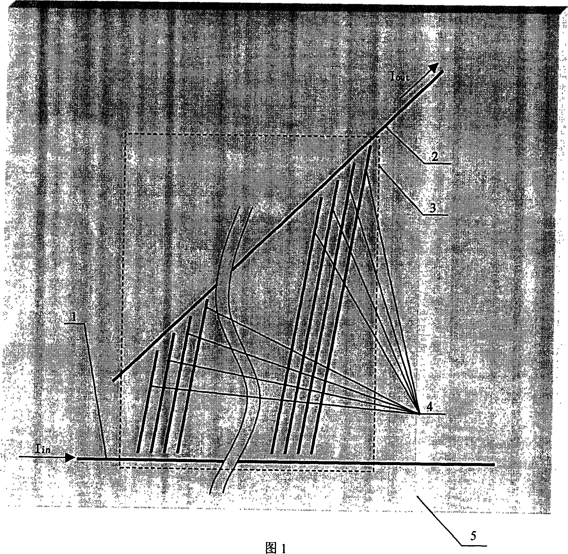
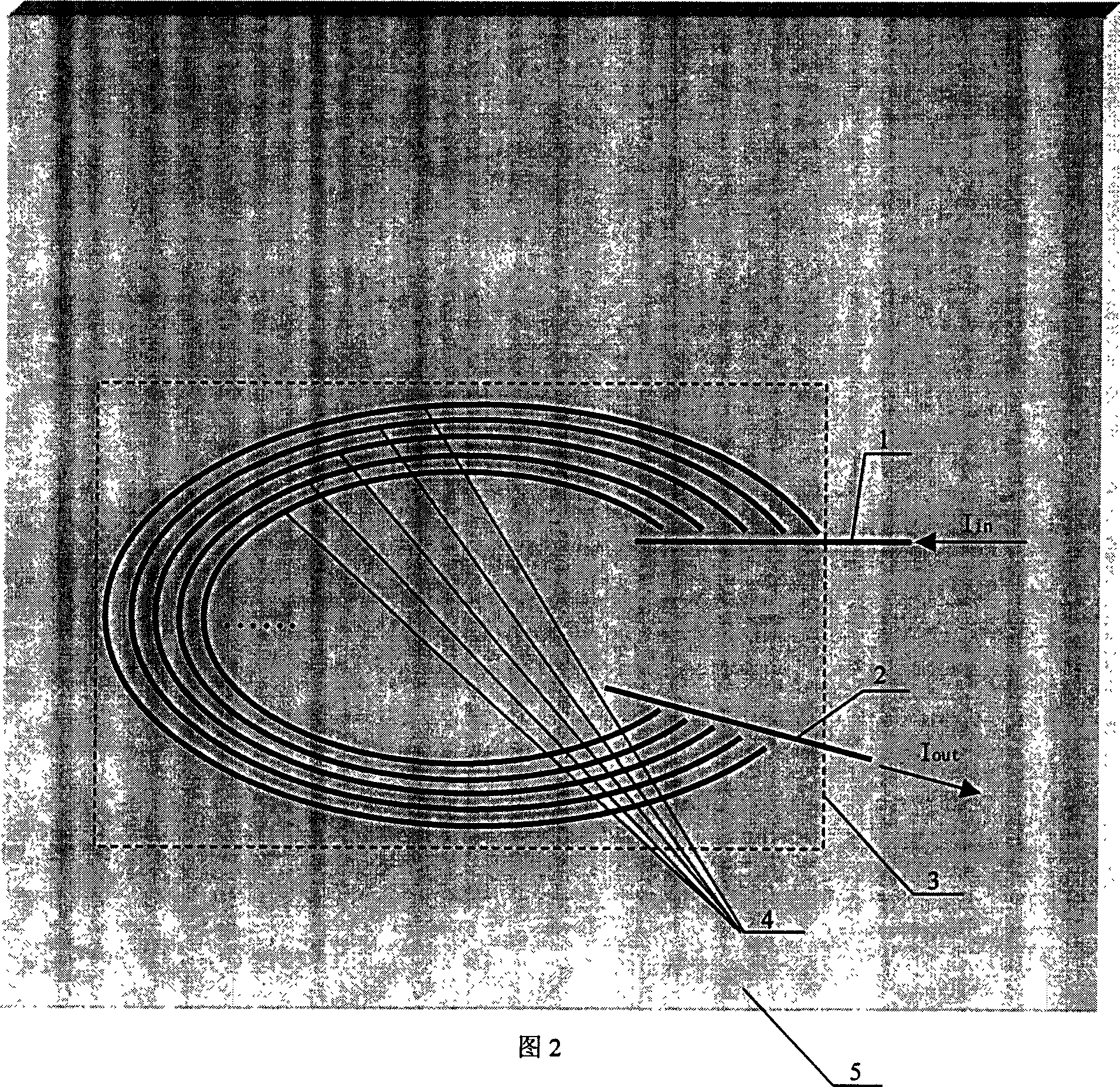
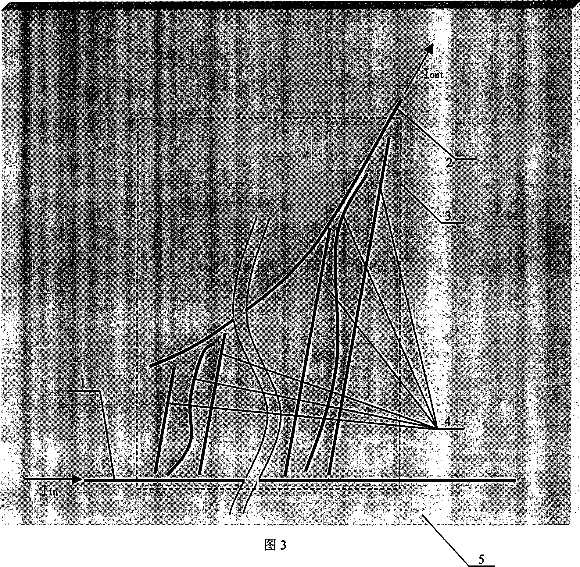
[0011] The arrayed waveguide interferometer in FIG. 1 includes an input optical waveguide 1, an output optical waveguide 2, and an arrayed optical waveguide 3 between them. The arrayed optical waveguide 3 is composed of no less than two optical waveguides 4. The array optical waveguide 3 is used to couple the optical wave field in the input optical waveguide 1 to the output optical waveguide 2 for interference superposition. In the figure, Iin and Iout represent the input and output light fields, respectively. In order to realize constructive interference, the light wave should be input from the input port of the input optical waveguide 1, and the optical path difference when passing through two adjacent optical waveguides 4 in the array optical waveguide 3 and reaching the output port of the output optical waveguide 2 is the wavelength of the output lig...


PUM


Abstract

The present invention relates to a waveguide technology and is one kind of waveguide array interferometer with wide application especially as kernel part in light communication network, light information transmitting and processing system, spectral measurement, sensing, laser device and integrated photoelectronic device. The waveguide array interferometer includes input light waveguide, output light waveguide, and waveguide array, linear and / or curved, on carrier between the input light waveguide and the output light waveguide. The present invention has the advantages of very high wavelength resolution or very narrow channel, modular structure and insertion loss not increasing with increased channel number. The waveguide array interferometer may be manufactured with high repeatability in the light mask technology similar to that in large-scale IC manufacture.

Description

technical field [0001] The invention relates to an arrayed waveguide interferometer, which belongs to the field of waveguide technology, and is especially suitable as a core device or key component of an optical communication network, optical information transmission and processing system, spectral measurement, sensing, laser device, and integrated optoelectronic device. Background technique [0002] Traditional interferometers include Fabry-Perot interferometers, Mach-Zehnder interferometers, Michelson interferometers, etc., which are widely used in various fields such as spectral analysis, laser devices, precision measurement, and photoelastic analysis. Many fiber optic sensors, such as stress, For strain, temperature, magnetic field optical fiber sensors, etc., a section of sensitized optical fiber that plays a sensing role is also used as a part of the above-mentioned interferometer to achieve sensing and measurement. In recent years, the rapid development of optical com...

Claims


Application Information

Patent Timeline
Patent Type & Authority Patents(China)
IPC IPC(8): G02B6/34
CPCG02B6/12009
Inventor 李志扬
Owner 李志扬
Learn More