

Small caster with buffer
A technology of buffers and small casters, which is applied in the direction of casters, wheels, transportation and packaging, etc., can solve the problems of large wheel position changes, road resonance, insufficient attenuation, etc., and achieve the effect of suppressing vibration and shaking
- Summary
- Abstract
- Description
- Claims
- Application Information
AI Technical Summary
Problems solved by technology
Method used
Image

Examples
Embodiment Construction
[0031] Embodiments of the present invention will be described below with reference to the accompanying drawings.
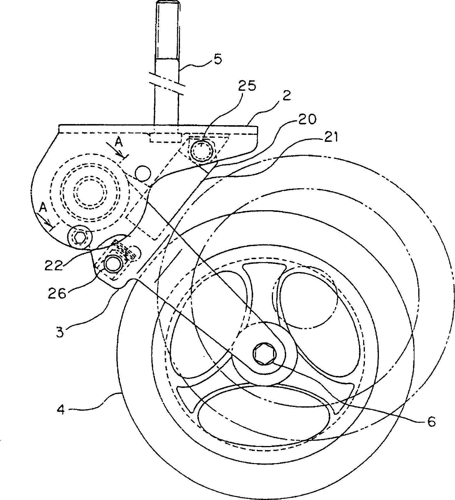
[0032] Such as figure 1 As shown, the caster has a bracket 2 connected to a vehicle body such as a wheelchair, a link 3 rotatably supported on the bracket 2 , and a wheel 4 rotatably supported on the front end of the link 3 . The wheel 4 is rotatably supported by a bolt 6 connected to the front end of the link 3 via a bearing not shown in the figure.
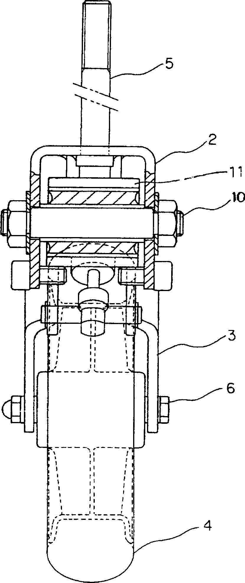
[0033] Such as figure 2 As shown, the bracket 2 has a U-shaped cross section, and is connected to the vehicle body through a bolt 5 passing through its upper part through a bearing not shown in the figure. The carriage 2 turns around a vertical axis (left-right direction), and the wheels 4 face the forward direction.
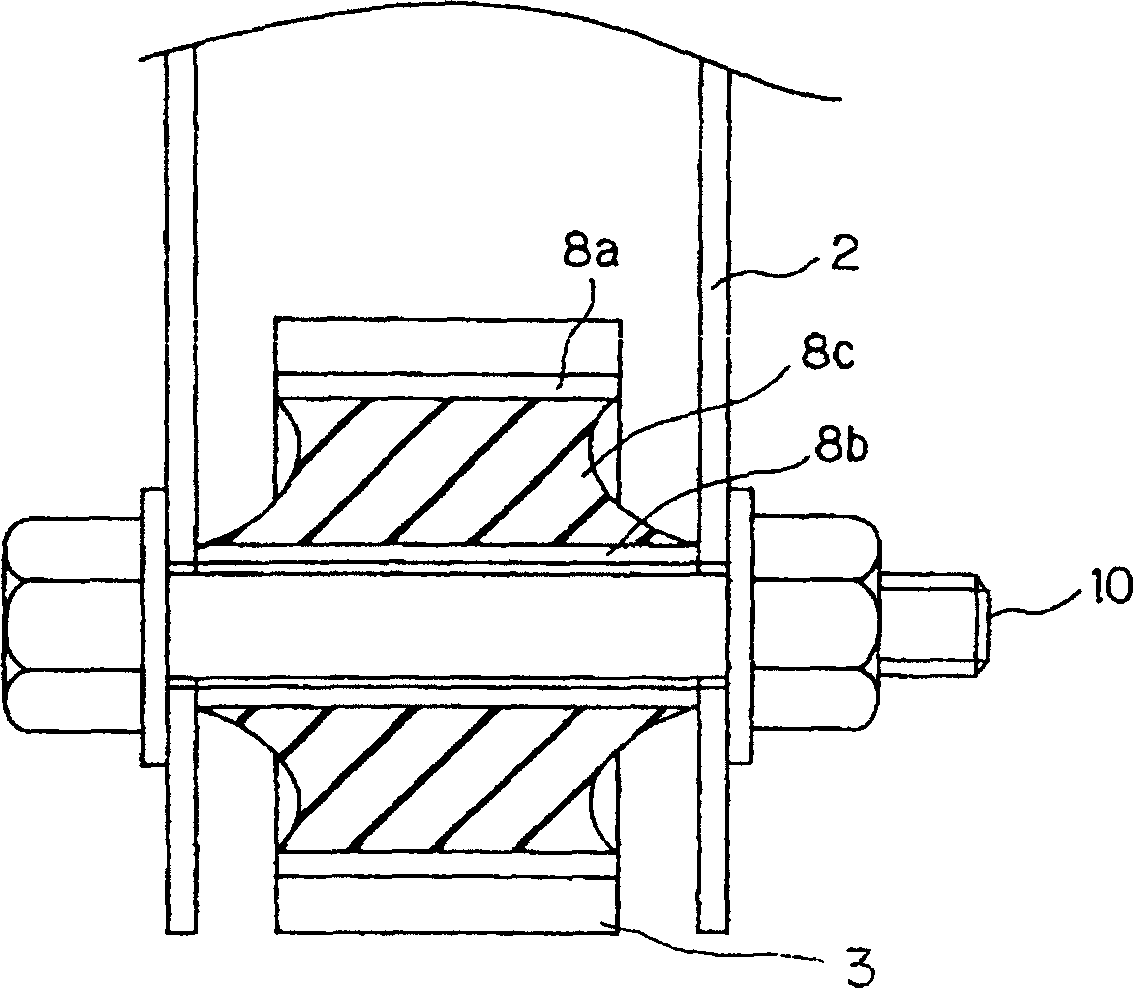
[0034] The connecting rod 3 is supported by the bracket 2 by the bolt 10, and can rotate about a horizontal axis (vertical direction) by twisting the rubber bush 8.
[0035] refer to image 3 It...
PUM
 Abstract
Description
Claims
Application Information