
Ignitor

An ignition device and injection nozzle technology, used in combustion ignition, intermittent spark ignition, igniter with fuel, etc., can solve the problems of complex structure, unavoidable foreign matter entry and adhesion, etc. failure, the effect of maintaining ignition performance

Inactive Publication Date: 2005-04-06
TOKAI
View PDF0 Cites 0 Cited by
  • Summary
  • Abstract
  • Description
  • Claims
  • Application Information

AI Technical Summary

Problems solved by technology

It is noted that the double serpentine type gas diffuser is effective in gas diffusion, but this is structurally complicated and cannot prevent the entry and attachment of foreign matter, or prevent malfunctions arising therefrom

Method used


Image

  • Ignitor
  • Ignitor
  • Ignitor

Examples


Embodiment Construction

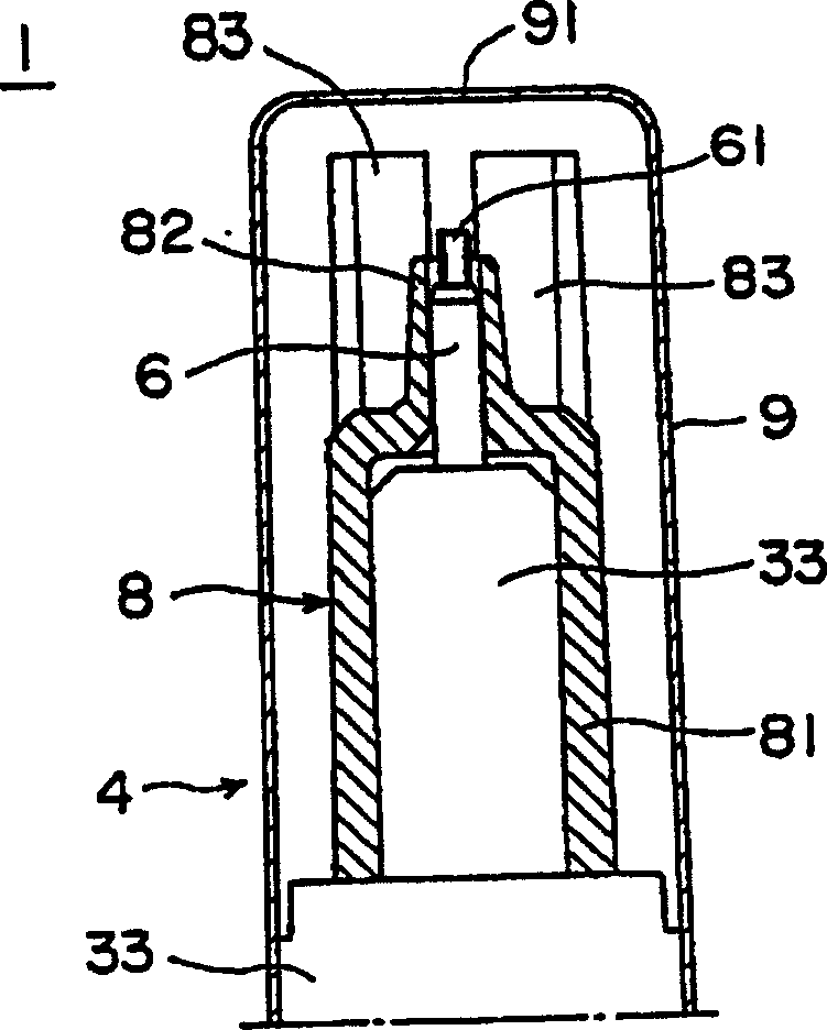
[0024] Now refer to the attached drawings in more detail and see first Figure 4 , It shows the ignition electrode 1 as a preferred embodiment of the ignition device according to the present invention. The ignition electrode (ignition device) 1 is composed of a pressure tank part 2 for containing high-pressure gas such as butane, a main body part 3 having a control device 5 (control knob) for completing the ignition operation, and a main body part 3 The part 3 is formed by the electrode part 4 extending forward.

[0025] The pressure tank part 2 of the ignition electrode 1 is composed of a cylindrical tank body 21 with a bottom, a blocking device 22 for blocking the opening of the tank body 21 and a tank cover 23. The blocking device 22 is equipped with a known valve mechanism 7 for supplying air to the blocking device 22. This valve mechanism 7 has a nozzle device 71 in its central part, and the nozzle device 71 is opened and closed by a generally L-shaped lever 72 installed at on...


PUM


Abstract

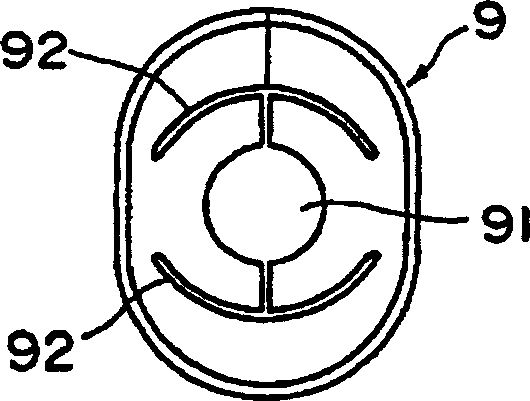
The present invention discloses a igniter used for complete the ignition of gas discharge, the igniter includes a gas spray jet from which the gas is injected, a jet holder made of an insulating material for supporting the said gas spray jet, and a cylindrical cap which a flame drills through and is mounted on the outer circumferential part of the said jet holder. The said jet holder has a cover part cap which is round the jet holder and has a jacket piece round the front end of the jet close to its outer limit, thereby enabling the diffusion of the gas expelled from the spray jet to be controlled.

Description

Technical field [0001] The present invention relates to a discharge type ignition device, in which electric discharge ignition is completed on injected gas, such as ignition electrode, gas igniter, etc., and more specifically to the structure of the nozzle part from which gas is injected . Background technique [0002] In discharge type ignition devices, such as ignition electrodes, piezoelectric gas igniters, etc., the gas injected by the injection nozzle is partially diffused into the air, which enhances the mixing with the air, so that it can be ignited even with weak electrical energy. In this way, the gas ignition performance using the discharge spark is enhanced. [0003] More specifically, a tubular nozzle spray head, or a diffuser, such as a diffusion coil, etc., is installed on the spray head of the nozzle from which the gas is injected. As a result of this installation method, the branch gas with a lower flow rate appears around the main flow of the injected gas, so tha...

Claims


Application Information

Patent Timeline
IPC IPC(8): F23Q3/00F23Q2/16F23Q2/36
CPCF23Q2/163
Inventor 齐藤正树
Owner TOKAI
Learn More