Medium-speed coal-mill direct-firing pulverizing combustion system for burning high-moisture lignite

A technology of combustion system and coal pulverizer, applied in combustion method, combustion equipment, block/powder fuel preparation, etc., can solve problems such as difficulty in adjusting means, and achieve the effect of ensuring ignition and combustion performance and improving drying ability

Inactive Publication Date: 2011-06-15
XIAN THERMAL POWER RES INST CO LTD
View PDF0 Cites 0 Cited by
  • Summary
  • Abstract
  • Description
  • Claims
  • Application Information

AI Technical Summary

Problems solved by technology

At the same time, judging from the results of operation and adjustment in recent years, it is difficult to find effective adjustment means to solve the above problems

Method used


Image

  • Medium-speed coal-mill direct-firing pulverizing combustion system for burning high-moisture lignite
  • Medium-speed coal-mill direct-firing pulverizing combustion system for burning high-moisture lignite
  • Medium-speed coal-mill direct-firing pulverizing combustion system for burning high-moisture lignite

Examples


Embodiment 1

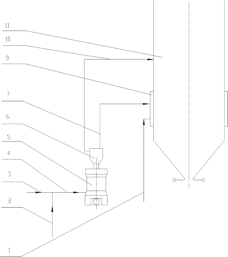
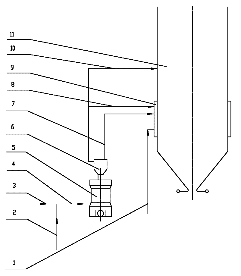
[0014] Embodiment 1: see figure 1 , the present invention includes a burner 9 arranged on the furnace 11 and a primary secondary air 1 connected to the burner 9, a medium-speed coal mill 5 is arranged outside the furnace 11, and the hot primary air 3 is mixed with the temperature-regulating air 2 to form After the drying air 4 is sent to the medium-speed coal mill 5, the outlet of the medium-speed coal mill 5 is provided with a pulverized coal concentrator 6, and the pulverized coal concentrator 6 separates the primary air-powder air flow into two phases, thick and thin, and sends them to the furnace 11 to participate in the process. combustion. The said dense-phase airflow is sent into the furnace 11 through the burner 9 as the primary wind powder airflow 7, and the rest of the light-phase airflow is directly sent into the upper part of the furnace 11 as OFA or SOFA10. Supplement the lack of secondary air momentum caused by the increase of primary air volume, so that a reaso...

Embodiment 2

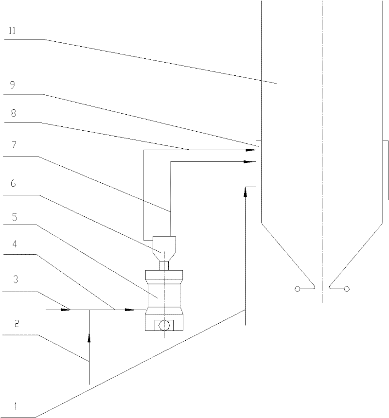
[0015] Example 2, see figure 2 , The dense-phase airflow of this embodiment is sent into the furnace 11 through the burner 9 as the primary wind powder airflow 7, and the remaining light-phase airflow is sent into the furnace chamber through the burner 9 as the secondary air 8. Supplementing the amount of oxygen required in the later stage of combustion and the lack of momentum of the secondary air caused by the increase of the primary air volume make the furnace organize a reasonable combustion dynamic field. Other connections are the same as in Embodiment 1.

[0016] The present invention divides one stream of air at the outlet of the original coal mill into two streams of thick and thin, the purpose of which is to increase the air volume at the inlet of the coal mill to solve the drying problem of high-moisture lignite, and at the same time reduce the primary air flow rate through the separation of the pulverized coal concentrator. And the primary wind speed is controlled...


PUM


Abstract

The invention provides a medium-speed coal-mill direct-firing pulverizing combustion system for burning high-moisture lignite, which can dry and burn high-moisture lignite. The system consists of a medium-speed coal mill, a pulverized coal concentrator and a burner. The system can adopt a primary air rate of over 40 percent to meet the drying capability of the system, and separates a primary air-powder current to be a dense-phase current and a thin-phase current through the pulverized coal concentrator on an outlet of the coal mill, wherein the dense-phase current enters a pulverized coal nozzle as primary air, and the remaining part of the current enters a furnace as secondary air, OFA or SOFA. The system has a good solution to the problem of drying high-moisture lignite, helps to organize a combustion power field in the furnace, and solves the problems that medium-speed coal-mill direct-firing pulverizing systems for burning high-moisture lignite are insufficient in drying capability, unbalanced in the ratio of primary air to secondary air, as well as momentum, not ideal in the combustion power field in the furnace, and the like.

Description

technical field [0001] The invention relates to a pulverizing combustion system of a lignite boiler, in particular to a medium-speed pulverizer direct-blown pulverizing combustion system using high-moisture lignite. Background technique [0002] Lignite is one of the main types of thermal coal in my country, accounting for about 18% of thermal coal reserves, mainly distributed in the northeast, Inner Mongolia and southwest regions. The main feature of lignite is high total moisture, which is a key factor in the selection of lignite boiler pulverization system. Traditional lignite boilers are generally equipped with a fan mill direct-blowing pulverizing system, using high-temperature furnace smoke, hot air and cold furnace smoke as drying media, which has a strong drying capacity, but the impact plate of the fan mill impeller wears quickly, and the maintenance workload is heavy. High cost and other problems. [0003] As the medium-speed pulverizer began to be used in domest...

Claims


Application Information

Patent Timeline
Patent Type & Authority Patents(China)
IPC IPC(8): F23K1/00F23K3/02
Inventor 白少林敬小磊晋中华李宗绪杨培军马建兰何仰朋刘定坡张峰赵卫东
Owner XIAN THERMAL POWER RES INST CO LTD
Why Eureka
Try Eureka