Power spring mechanism and equipment having mechanism

A clockwork and machine technology, applied in the structural field of the drive mechanism, can solve the problems of difficult braking characteristics, high sealing, complex clockwork casings, etc.

Inactive Publication Date: 2005-05-11
SEIKO EPSON CORP
View PDF1 Cites 0 Cited by
  • Summary
  • Abstract
  • Description
  • Claims
  • Application Information

AI Technical Summary

Problems solved by technology

[0004] However, in the clockwork mechanism with the above-mentioned braking device, although the structure including the clockwork spring, the clockwork case, the brake plate and the brake case is provided, especially because the brake case accommodating the brake plate The interior needs to be filled with a fluid substance, so it needs high sealing performance. In addition, because the brake plate and the spring need to be connected together, it usually has a complicated structure, and the number of parts is also large, which makes it very difficult to reduce manufacturing cost issue
In addition, because the shape and structure are complicated, the spring case and the like are also complicated. If it is not a plastic molded product, it is impossible to manufacture it at low cost. In this case, it often leads to insufficient rigidity of the mechanism or insu

Method used


Image

  • Power spring mechanism and equipment having mechanism
  • Power spring mechanism and equipment having mechanism
  • Power spring mechanism and equipment having mechanism

Examples


Embodiment Construction

[0111] Hereinafter, embodiments of the clockwork mechanism of the present invention and the machine equipped with the clockwork mechanism will be described in detail with reference to the accompanying drawings.

[0112] [the first embodiment]

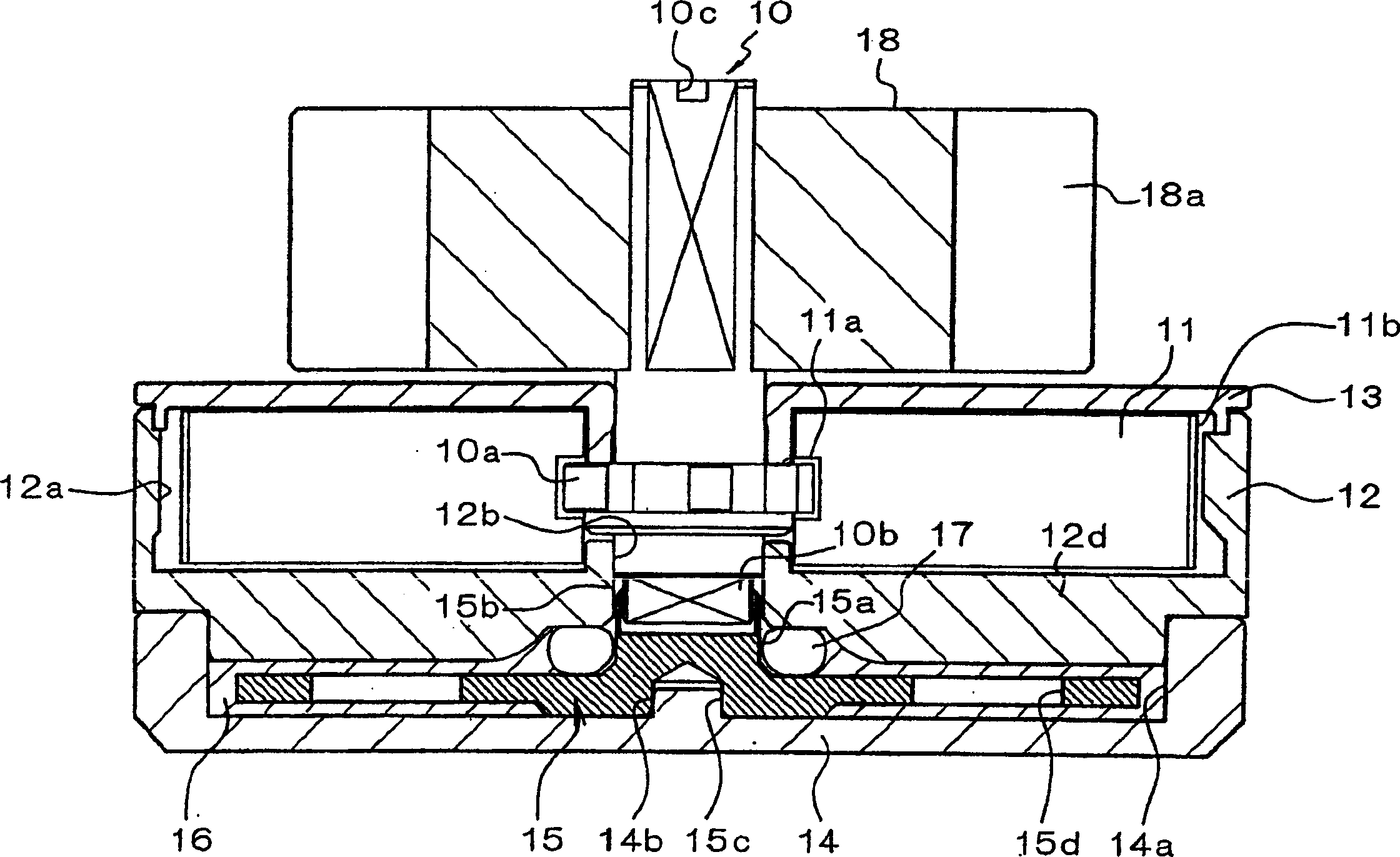
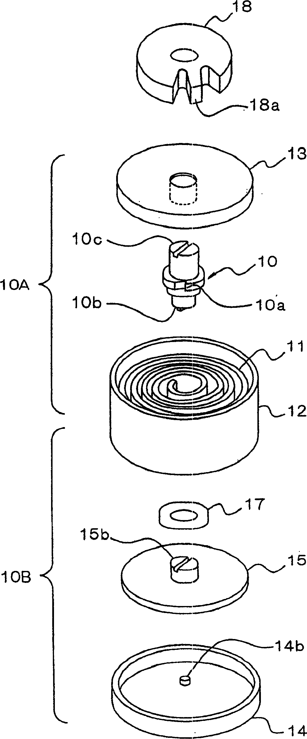
[0113] figure 1 A longitudinal sectional view showing a first embodiment of the clockwork mechanism of the present invention, figure 2 An exploded perspective view of the first embodiment is shown. In this embodiment, there is a shaft-shaped winding stem 10 constituting a rotating member, a spiral mainspring 11 connected to a mounting portion 10a of the winding stem 10 with an inner end 11a, and a winding stem 11 for accommodating the mainspring 11. Bar box 12 and barrel cover 13 of barrel box. The barrel 12 and the barrel cover 13 pivotally support the above-mentioned winding stem 10 , and the outer peripheral inner surface of the barrel 12 surrounding the mainspring accommodating portion 12 a is connected to the outer end 11 b of ...


PUM


Abstract

The winding stem (10) is connected with the inner end (11a) of the mainspring (11), and the outer end (11b) of the mainspring (11) is connected with the barrel (12). A brake plate (15) is arranged inside the brake housing (11) and filled with a fluid substance (16). In addition, a concave-convex joint (10b) is provided at the lower end of the winding stem (10), and the concave-convex joint (10b) and the concave-convex joint (15) of the brake plate (15) arranged in the brake housing (14) are provided. 15b) Snap-in. In the above structure, the spring mechanism can be miniaturized and the manufacturing cost can be reduced by adopting a structure that simplifies the structure of the spring mechanism having the braking device and reduces the number of parts.

Description

technical field [0001] The present invention relates to a clockwork mechanism and a machine equipped with such a clockwork mechanism, especially a structure suitable for a driving mechanism such as an automatic retractable mechanism, a retractable mechanism, etc. of a cover or a container. Background technique [0002] Conventionally, a small spring mechanism has been widely used in various fields as a driving source for obtaining driving force for various articles. Usually, the inside of the spring case called the barrel accommodates a spiral spring, and a rotating shaft connected to the inner end of the spring is pivotally supported at the center of the spring case. In this case, There is also a case where only the rotating shaft is used as the only driving force extraction part, but, for example, either one of the rotating shaft and the mainspring case is used as an input shaft, and the other is used as an output shaft. [0003] In the above-mentioned clockwork mechanism...

Claims


Application Information

Patent Timeline
IPC IPC(8): A63H29/04F03G1/02F16F1/08F16F1/10F16F9/12
CPCA63H29/04F03G1/02F16F1/08F16F1/10F16F9/12G04B1/10
Inventor 长尾昭一守国荣时松永太郎
Owner SEIKO EPSON CORP
Why Eureka
Try Eureka