
Self-energizing brake caliper

a self-energizing, brake caliper technology, applied in the direction of braking systems, mechanical devices, transportation and packaging, etc., can solve the problems of low productivity and high manufacturing cost, complex structure of self-energizing brakes according to prior arts, and inapplicability of self-energizing brakes, etc., to achieve excellent braking force

Active Publication Date: 2020-04-23
KYUNG CHANG IND +1
View PDF0 Cites 2 Cited by
  • Summary
  • Abstract
  • Description
  • Claims
  • Application Information

AI Technical Summary

Benefits of technology

The present patent aims to solve the problems in the prior art by providing a self-energizing brake caliper that does not have self-locking while amplifying the braking force generated by a hydraulic cylinder or a motor. This results in an excellent braking force.

Problems solved by technology

The self-energizing brake according to the prior arts has complex structure, low productivity and high manufacturing costs.
In particular, many reasons including self-locking effects in the wedge structure makes the self-energizing brake inapplicable.

Method used


Image

  • Self-energizing brake caliper
  • Self-energizing brake caliper
  • Self-energizing brake caliper

Examples


Embodiment Construction

[0023]Hereinafter, the present disclosure will be described in detail with reference to the accompanying drawings. As those skilled in the art would realize, the described embodiments may be modified in various different ways, all without departing from the spirit or scope of the present disclosure.

[0024]The terminology used herein is for the purpose of describing particular embodiments only and is not intended to be limiting of the disclosure. As used herein, the singular forms “a,”“an,” and “the” are intended to include the plural forms as well, unless the context clearly indicates otherwise. It will be further understood that the terms “comprise” and / or “comprising,” when used in this specification, specify the presence of stated features, integers, steps, operations, elements, and / or components, but do not preclude the presence or addition of one or more other features, integers, steps, operations, elements, components, and / or groups thereof. As used herein, the term “and / or” in...


PUM


Abstract

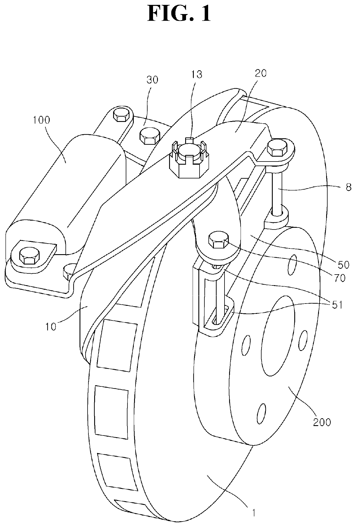
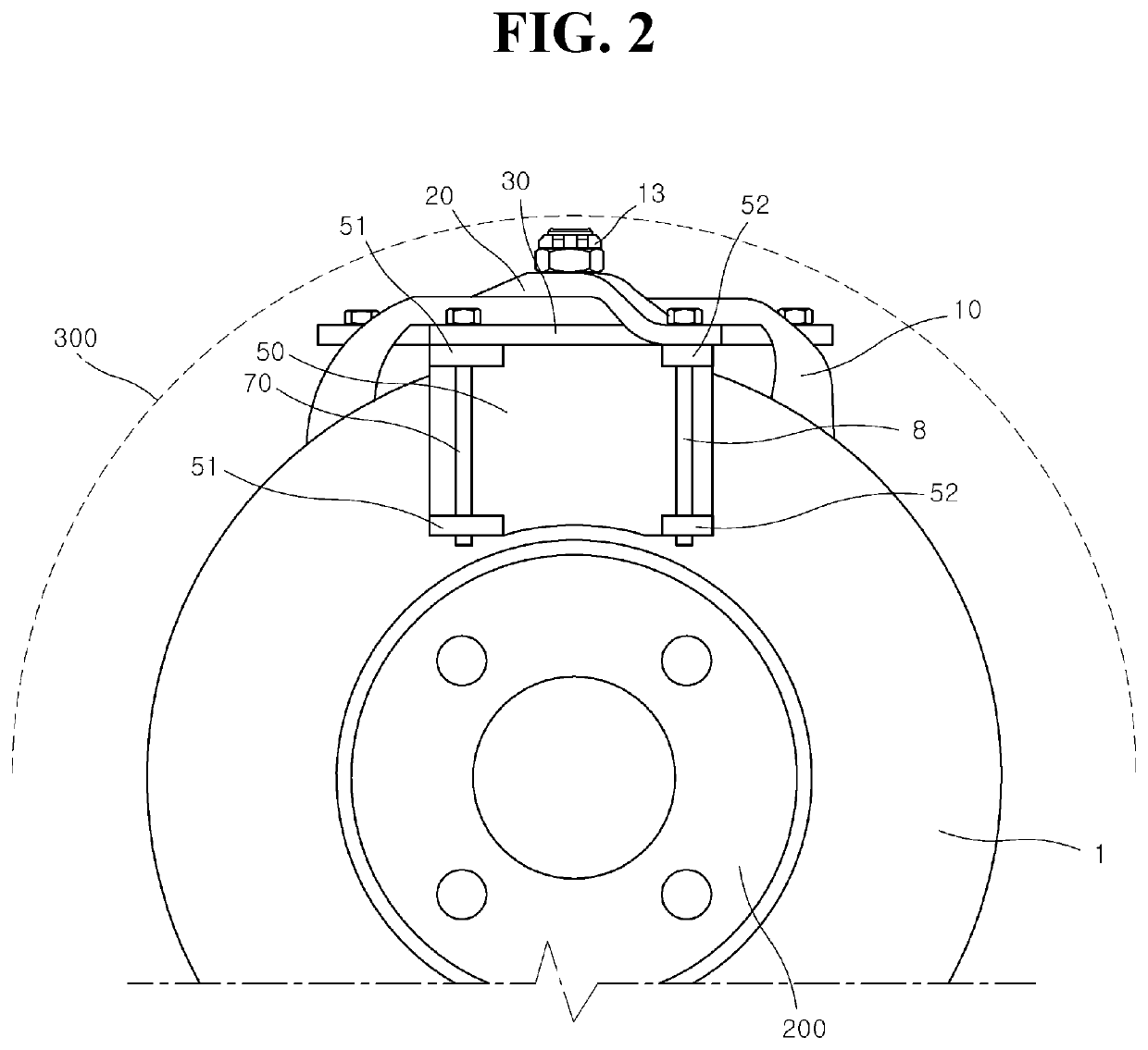
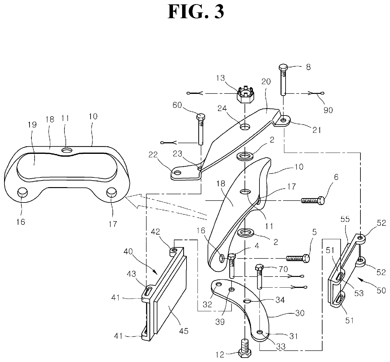
According to the present disclosure, there is provided a self-energizing brake caliper which comprises a caliper bracket fixed to a vehicle frame and comprising a rotation axis extending in the height direction of the vehicle; a first caliper arm rotatably connected to the rotation axis; a second caliper arm rotatably connected to the rotation axis and crossing the first caliper arm; an inboard brake pad; and an outboard brake pad. The first caliper arm is slidably connected at a first end of the inboard brake pad in the inboard side of the brake disc and the outer end of the first caliper arm is connected to a second end of the outboard brake pad. The second caliper arm is connected to the second end of the inboard brake pad in the inboard side of the brake disc and the outer end of the second caliper arm is slidably connected to the first end of the outboard brake pad. The driving force of an actuator is transferred to the inner ends of the first caliper arm and the second caliper arm.

Description

CROSS-REFERENCE TO RELATED APPLICATION[0001]The present application claims priority to Korean Patent Application No. 10-2018-0125673 filed on Oct. 22, 2018, the entire contents of which are incorporated herein by reference.TECHNICAL FIELD[0002]The present disclosure relates to a self-energizing brake caliper.BACKGROUND ART[0003]In a hydraulic brake system, a driver presses a brake pedal so that the pressure generated by a master cylinder is transferred to braking force by disc brake caliper or drum brake wheel cylinder. A self-energizing brake for amplifying the braking force has been known. For example, the self-energizing brake using a ball and ramp is disclosed by U.S. Pat. No. 5,012,901 and the self-energizing brake using wedge-effect is disclosed by U.S. Pat. No. 6,318,513, U.S. Patent Application Publication Nos. 2008 / 0230330A1 and 2009 / 0065311A1.[0004]The self-energizing brake according to the prior arts has complex structure, low productivity and high manufacturing costs. In...

Claims


Application Information

Patent Timeline
IPC IPC(8): F16D55/2255F16D65/00F16D65/18B60T1/06
CPCF16D2055/0008F16D65/0075F16D2055/002F16D65/18F16D2125/68F16D55/2255F16D65/0056B60T1/065F16D2125/64F16D65/092F16D2125/70F16D55/2245F16D65/095F16D2125/60F16D2121/04F16D2121/24F16D51/50F16D2055/0029
Inventor LEE, KWANGJIN MICHAEL
Owner KYUNG CHANG IND
Learn More