Symbol combiner synchronization after jump to new time alignment and long-distance unit using the method

A remote unit, time technology, applied in the communication between multiple stations, electrical components, advanced technology and other directions, can solve problems such as inability to system time alignment and demodulation

Inactive Publication Date: 2005-06-08
QUALCOMM INC
View PDF12 Cites 0 Cited by
  • Summary
  • Abstract
  • Description
  • Claims
  • Application Information

AI Technical Summary

Problems solved by technology

If the sleep timer is not programmed in multiples of 80ms, when the demodulator activates the PN generator and / or interleaver, the timing will not be aligned with the proper system time and demodulation will not be possible

Method used


Image

  • Symbol combiner synchronization after jump to new time alignment and long-distance unit using the method
  • Symbol combiner synchronization after jump to new time alignment and long-distance unit using the method
  • Symbol combiner synchronization after jump to new time alignment and long-distance unit using the method

Examples


Embodiment Construction

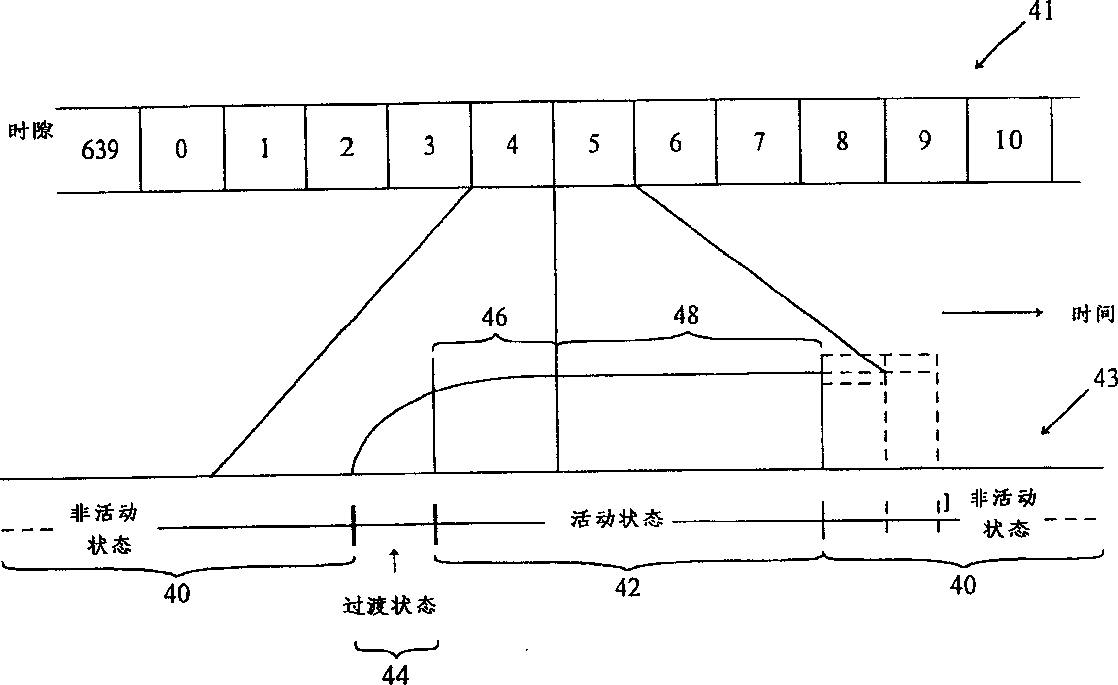
[0026] figure 2 A schematic diagram showing a transition from an inactive state to an active state at a time slot allocated by a remote unit in a slotted mode communication system. figure 2 Consists of two separate parts. The upper part 41 represents the continuous sequence of time slots in which time passes from left to right. The lower portion 42 represents the events that occur during transitions between the active and inactive states of the remote unit in a slotted mode communication system, where slot 5 is the assigned slot. The lower time scale has been expanded so that transitions can be shown in more detail.

[0027] in particular, figure 2 The lower portion 43 of , shows the transition from the inactive state 40 to the active state 42 . In the active state 42 the remote unit monitors the base station signal during at least a portion of time slot 5 . Before time slot 5 begins, the remote unit transitions from inactive state 40 to active state 42 via transition sta...


PUM


Abstract

A method and apparatus wherein a remote unit (10A, 10B and 10C) in a slotted mode wireless communication system can calculate the precise time of its entire active state. In the remote units (10A, 10B and 10C), "wall clock time" is calculated from a modulo 80 counter known as the combiner time counter (224). When a remote unit (10A, 10B and 10C) enters its inactive state, counters in the remote unit (10A, 10B and 10C), including the combined time counter, are deactivated. When the remote unit (10A, 10B and 10C) re-enters its active state, the value in the combiner time counter (224) may be incorrect relative to the slotted mode time. The controller (106) in the remote units (10A, 10B and 10C) forces the combiner time count to the correct phase, causing the combiner (224) to be within the correct value of 26.66. The controller (106) then determines a combiner offset to compensate for any remaining error in the combiner time counter (224). Control (106) can then use the combiner time counter (224) and combiner offset to calculate the exact wall clock time. When convenient, such as at a slot boundary, the remote units (10A, 10B and 10C) can reset the combiner counter (224) to the correct value and set the combiner offset to zero.

Description

field of invention [0001] The invention relates to the field of wireless communication. More particularly, the present invention relates to reducing the power consumption of remote units in wireless communication systems using slotted paging. Background of the invention [0002] A wireless communication system may include multiple remote units and multiple base stations. FIG. 1 illustrates an embodiment of a terrestrial wireless communication system having three remote units 10A, 10B, and 10C and two base stations 12 . In FIG. 1, the three remote units are shown as a mobile phone unit 10A installed in the car, a remote portable computer 10B and a fixed location unit 10C (such as may be found in a wireless local loop or meter reading system). The remote unit may be any type of communication unit (such as a handheld personal communication unit), portable data unit (such as a personal data assistant), or fixed location data unit (such as a meter reading device). FIG. 1 shows...

Claims


Application Information

Patent Timeline
Patent Type & Authority Patents(China)
IPC IPC(8): H04B7/26H04B1/7075H04B1/7115
CPCH04B1/70756H04B1/7115Y02D30/70H04B1/707
Inventor A·诺伊菲尔德
Owner QUALCOMM INC
Why Eureka
Try Eureka