Circuit structure and signal encode method for decreasing number of interface signals for serial ATA separated physical layer
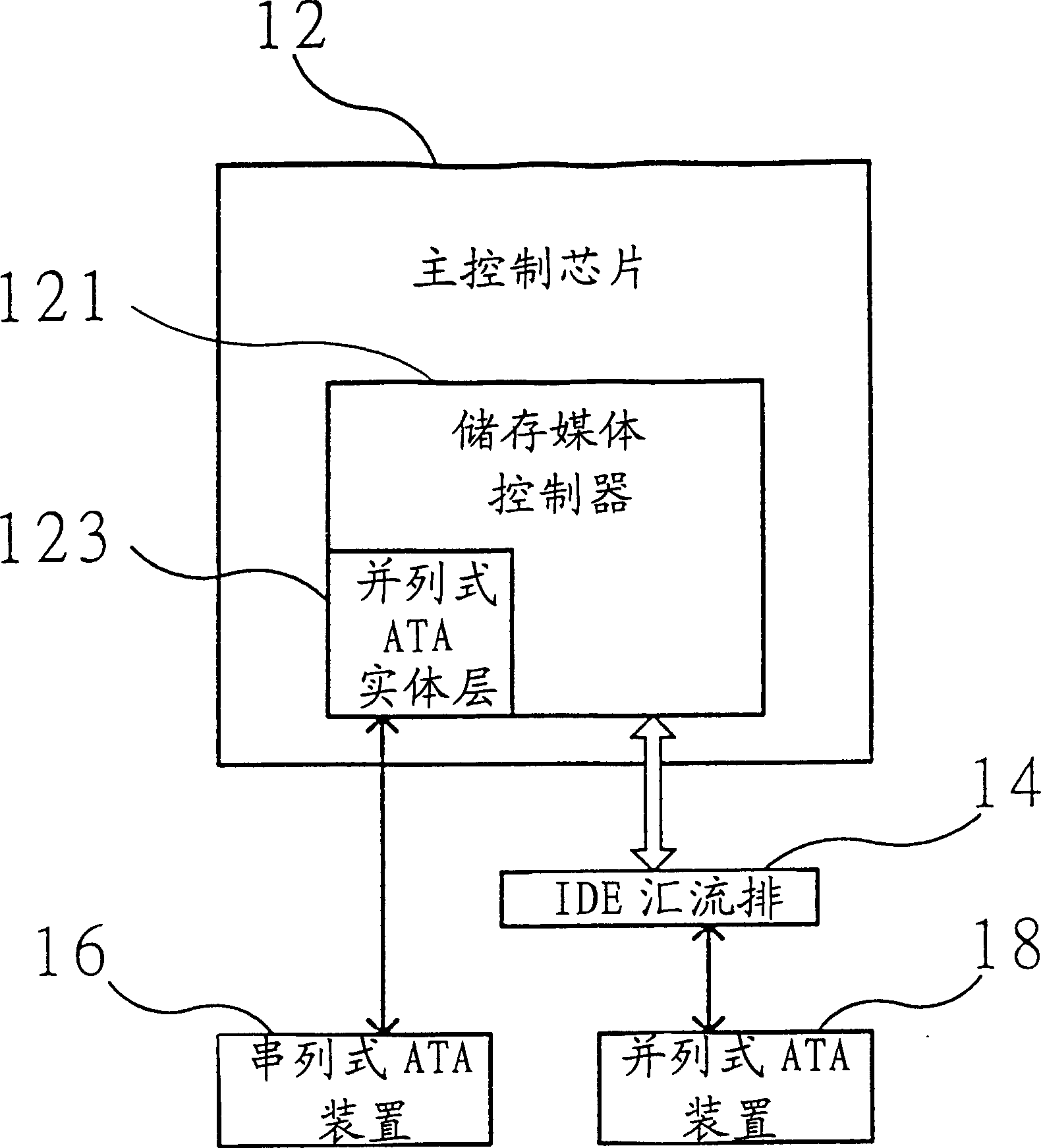
A serial, physical layer technology, applied in electrical digital data processing, instruments, etc., can solve the problems of occupying a large area, difficult to control the pass rate, and the area of the main control chip 12 is large, and achieve the effect of reducing interface signals.
- Summary
- Abstract
- Description
- Claims
- Application Information
AI Technical Summary
Problems solved by technology
Method used
Image
Examples
Embodiment Construction
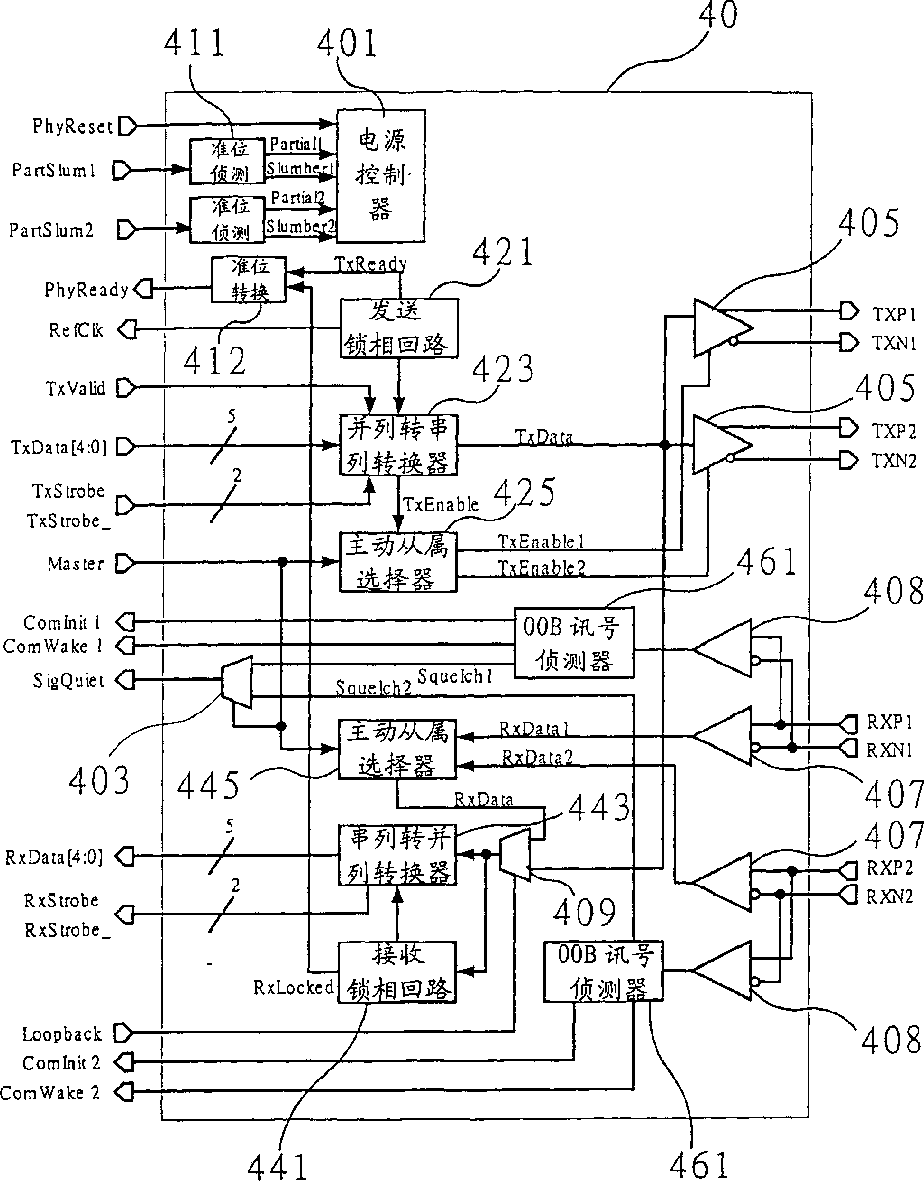
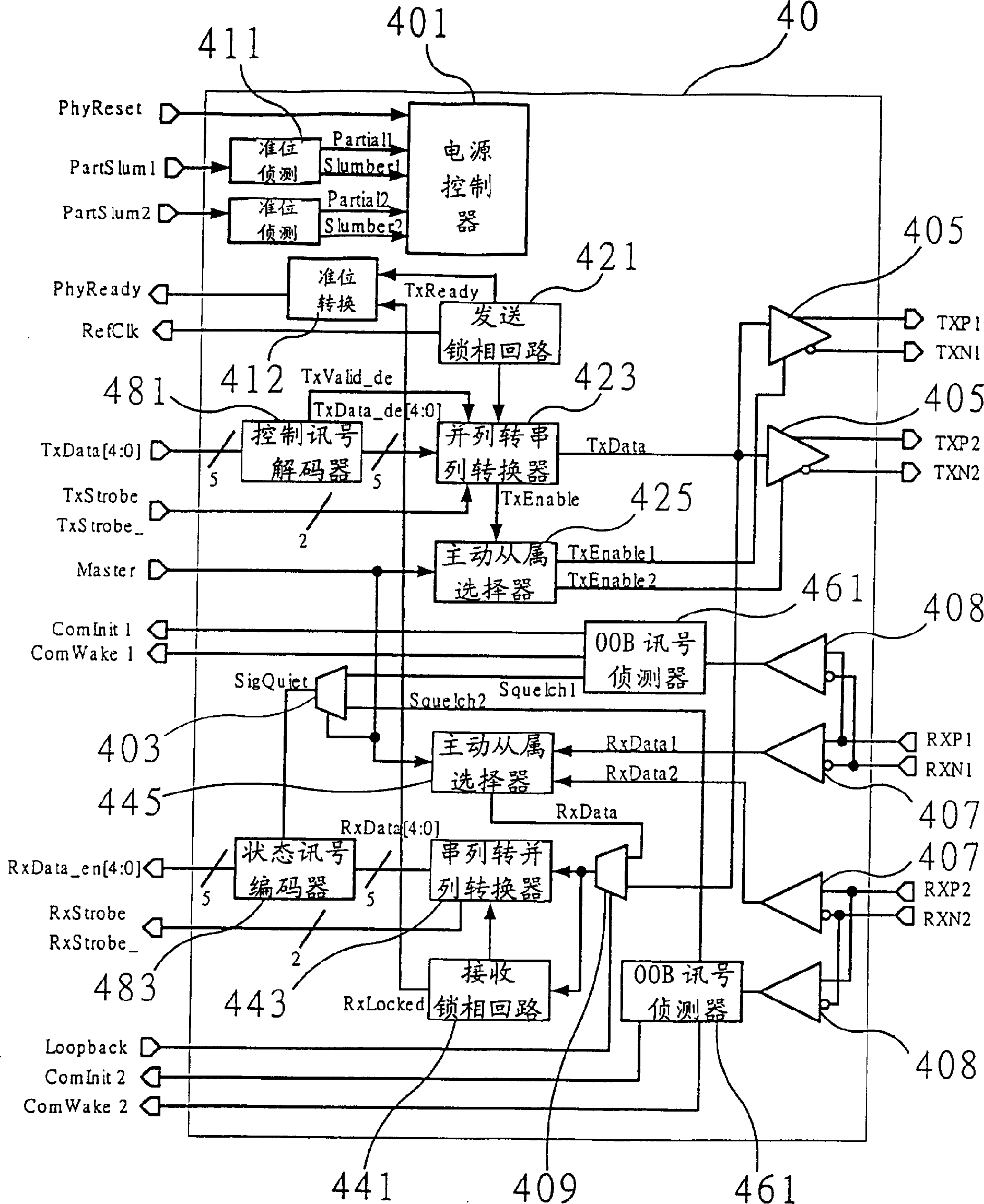
[0046] First, see figure 2 , is a circuit block diagram of a split physical layer chip in a preferred embodiment of the present invention. As shown in the figure, its main structure includes: a parallel serial converter (serialize / deserializer; SerDes), a phase locked loop (phase locked loop; PLL), at least one transmitter (transmitter) 405, at least one receiver A receiver 407 and at least one OOB signal detector 461 .
[0047] The components required for the tandem ATA physical layer under the framework of the present invention are designed in two chips according to the circuit characteristics. The separate physical layer chip 40 includes all high-frequency analog circuits, and the other physical layer circuits are digital. The main circuit is integrated in the storage media controller, such as the coder (8BlOBencoder) that converts the 8bits signal and control signal of parallel ATA into 10bits signal and converts the 10bits signal from serial ATA signal into 8bits signal...
PUM
 Abstract
Description
Claims
Application Information
 - R&D
- Intellectual Property
- Life Sciences
- Materials
- Tech Scout
- Unparalleled Data Quality
- Higher Quality Content
- 60% Fewer Hallucinations
Browse by: Latest US Patents, China's latest patents, Technical Efficacy Thesaurus, Application Domain, Technology Topic, Popular Technical Reports.
© 2025 PatSnap. All rights reserved.Legal|Privacy policy|Modern Slavery Act Transparency Statement|Sitemap|About US| Contact US: help@patsnap.com


