
Automobile parking braking method and hydraulic parking brake device

A brake device and brake fluid technology, applied in the direction of brake transmission device, hydraulic brake transmission device, manual start device, etc., can solve the problem of small braking force, braking stop, unsuitable for parking, etc. problem, to achieve the effect of small steering force and large braking force

Inactive Publication Date: 2005-07-06
曹显亮
View PDF1 Cites 0 Cited by
  • Summary
  • Abstract
  • Description
  • Claims
  • Application Information

AI Technical Summary

Problems solved by technology

[0002] The current method of parking brakes for automobiles generally uses mechanical transmission to realize parking brakes; For car braking, let alone the lever ratio between the brake lever and the pressure end of the brake system should be changed with the lever ratio required by various braking states, because the human physical strength is limited, so its braking effect less force
It is impossible to quickly brake the moving vehicle. If the brake clearance has not been adjusted for a long time, the vehicle that has stopped on the slope cannot brake the parked vehicle.
Chinese patent announcement number 2359183Y discloses a kind of " automobile brake device " that is used for automobile hydraulic brake system, and it utilizes control valve to control accumulator to increase hydraulic braking force, but this accumulator structure is complicated, existing automobile It has no design itself, and it needs power when storing energy, so it is neither suitable for parking nor used for car modification

Method used


Image

  • Automobile parking braking method and hydraulic parking brake device
  • Automobile parking braking method and hydraulic parking brake device
  • Automobile parking braking method and hydraulic parking brake device

Examples


Embodiment Construction

[0016] The present invention is described in more detail below with specific embodiment in conjunction with accompanying drawing:

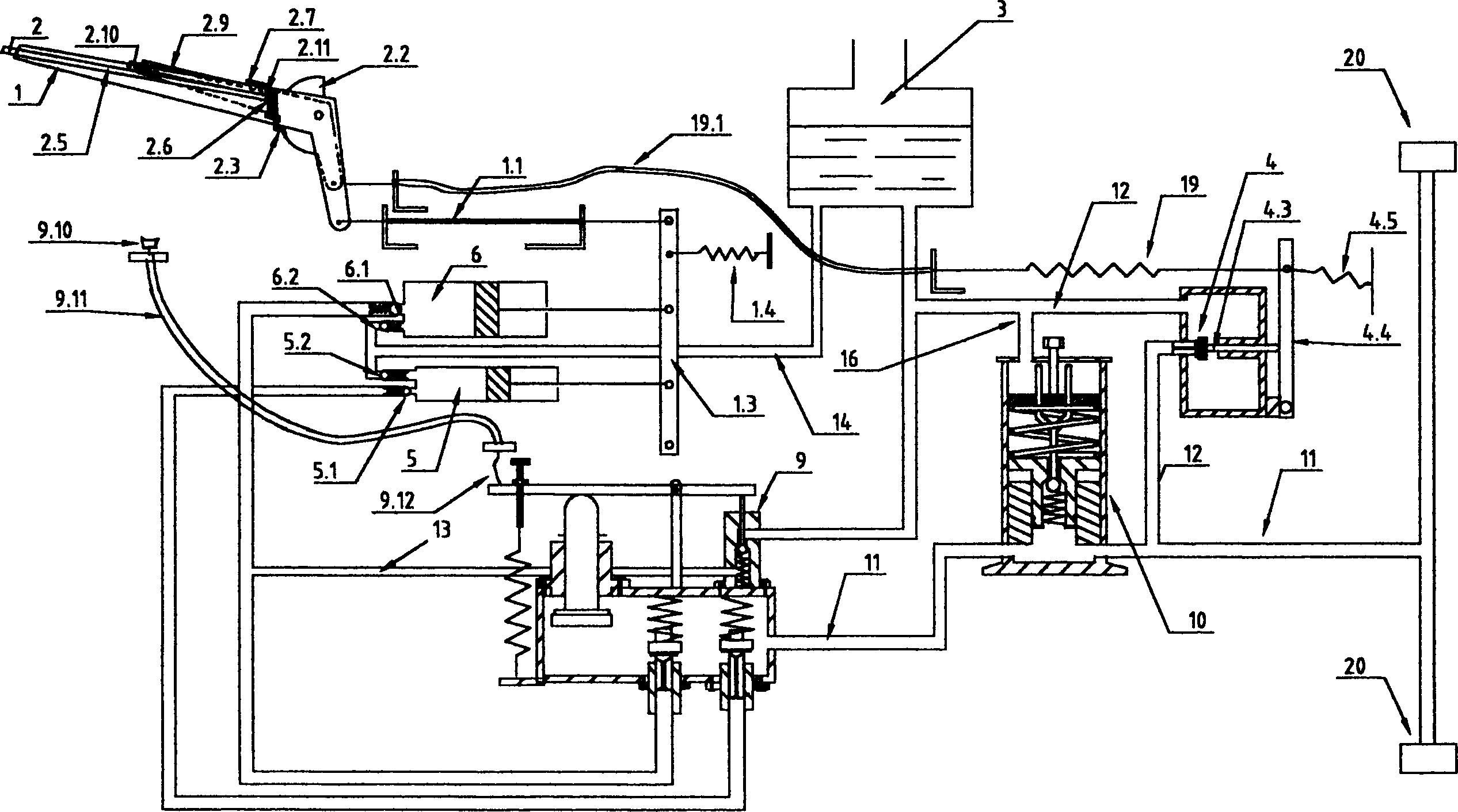
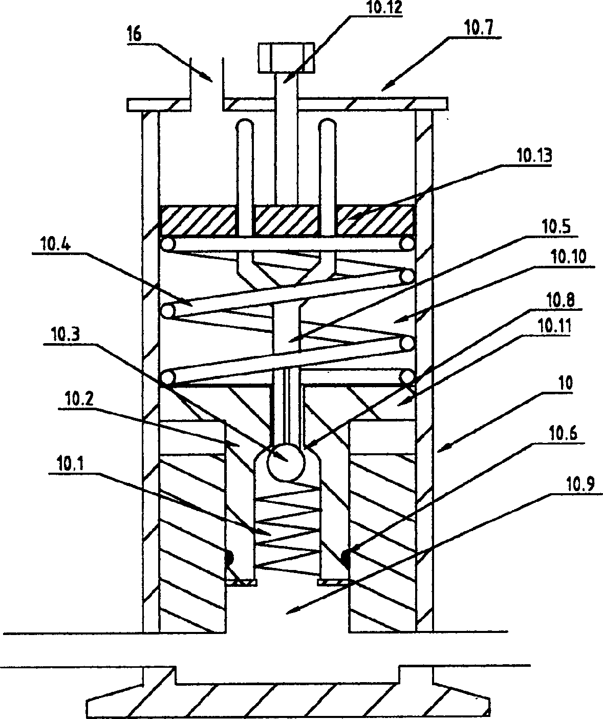
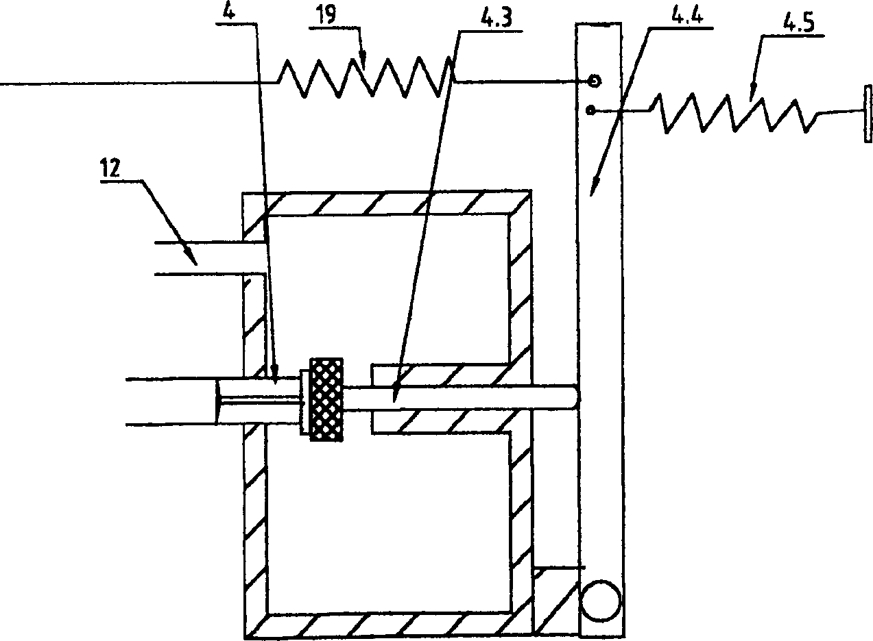
[0017]A hydraulic parking brake device for parking brakes of automobiles, which includes a liquid storage chamber 3, a brake handle 1, a brake release handle 2.9, a brake release valve 4, a high-pressure brake master cylinder 5, a low-pressure brake Brake master cylinder 6, low pressure brake master cylinder pressure limiting valve 9, low pressure brake master cylinder pressure limiting valve manual handle 9.10, low pressure brake master cylinder pressure limiting valve control room 18 high pressure energy storage pressure limiting pressure applicator 10 each Dynamic sub-cylinder 20 and corresponding pipelines; it is characterized in that: the brake master cylinder is provided with two-way liquid infusion pipelines, and the liquid outlet check valve 5.1 is connected in series on the liquid outlet pipeline of the high-pressure brake master cylinder ...


PUM


Abstract

The invention relates to a parking brake method of an automobile; it uses the driver's physical strength to brake to generate a certain amount of high-pressure brake fluid and energy, stores them, and then uses the stored high-pressure brake fluid and energy to implement the parking brake; the lever ratio between its brake lever and the pressure section of the brake system can be changed according to the needs of various braking states; it can also be increased according to the needs of various braking states. Reduce the number of brake master cylinders to implement the braking effect. According to the aforementioned method, the present invention has also designed a hydraulic parking brake device for automobile parking brake, which includes a liquid storage chamber, a brake handle, a brake release handle, a brake release valve, and a high-pressure brake master cylinder. , low-pressure brake master cylinder, low-pressure brake master cylinder pressure-limiting valve, high-pressure energy storage pressure-limiting pressure applicator, each brake sub-cylinder and corresponding pipelines; the invention is mainly used for parking brakes of automobiles. It can also be used as a service brake when the service brake fails.

Description

technical field [0001] The invention relates to an automobile parking braking method; the invention also relates to an automobile hydraulic parking braking device. Background technique [0002] The current method of parking brake of automobile generally utilizes mechanical transmission to realize parking brake; For car braking, let alone the lever ratio between the brake lever and the pressure end of the brake system can be changed with the lever ratio required by various braking states, because the human physical strength is limited, so its braking effect The force is relatively small. Just can't brake the vehicle that is running and stop very fast, if the brake gap has not been adjusted for a long time, the vehicle that has stopped on the slope can't brake the parked vehicle. Chinese patent announcement number 2359183Y discloses a kind of " automobile brake device " that is used for automobile hydraulic brake system, and it utilizes control valve to control accumulator t...

Claims


Application Information

Patent Timeline
Patent Type & Authority Patents(China)
IPC IPC(8): B60T7/08B60T11/10B60T13/12B60T13/14B60T17/00
Inventor 曹显亮
Owner 曹显亮
Learn More