Drive method for camera shutter

A camera and shutter technology, applied in the direction of cameras, shutters, installation, etc., can solve the problem of reduced sensitivity of electronic switches

Inactive Publication Date: 2005-07-06
SAMSUNG ELECTRONICS CO LTD
View PDF4 Cites 0 Cited by
  • Summary
  • Abstract
  • Description
  • Claims
  • Application Information

AI Technical Summary

Problems solved by technology

In this type of method, in order to control the focus, the focus control ring must be turned from the initial position to a specific position, so the distance to control the focus is longer and the sensitivity of the electronic switch is reduced

Method used


Image

  • Drive method for camera shutter
  • Drive method for camera shutter
  • Drive method for camera shutter

Examples


Embodiment Construction

[0047] Preferred embodiments of the present invention will be described in detail with reference to the accompanying drawings.

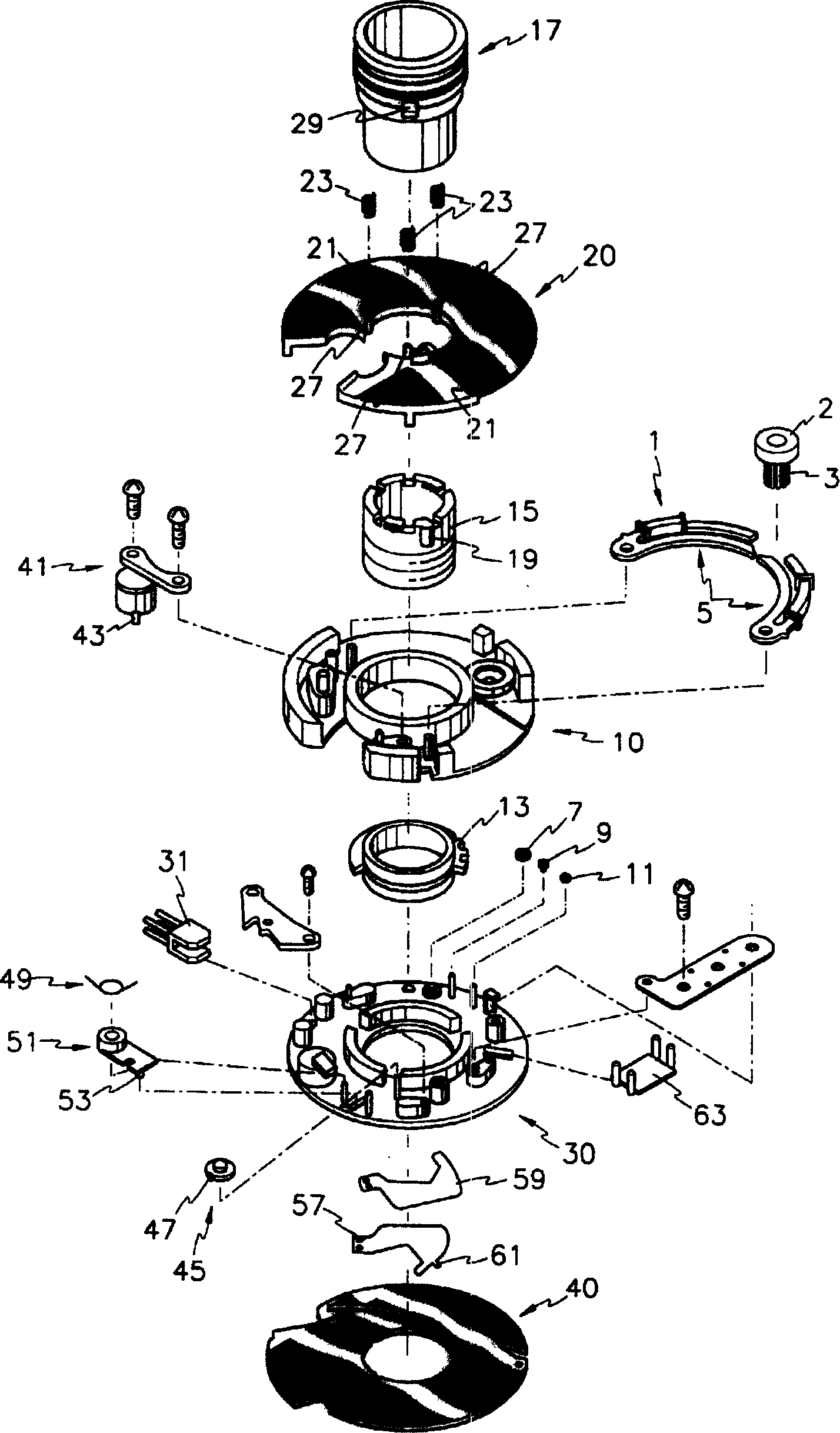
[0048] figure 1 Shown is a detailed perspective view of an electronic shutter driving device for a camera according to a preferred embodiment of the present invention.

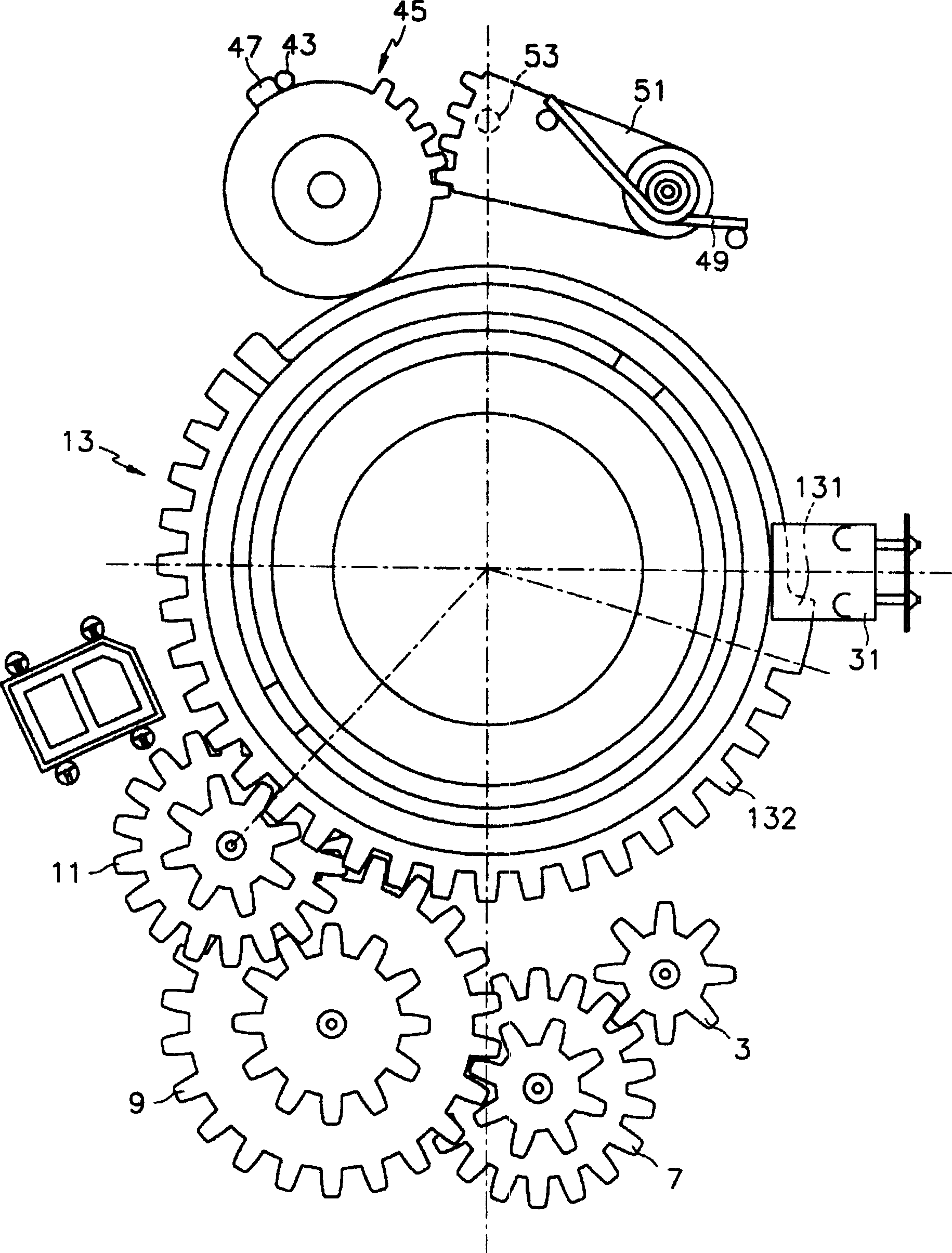
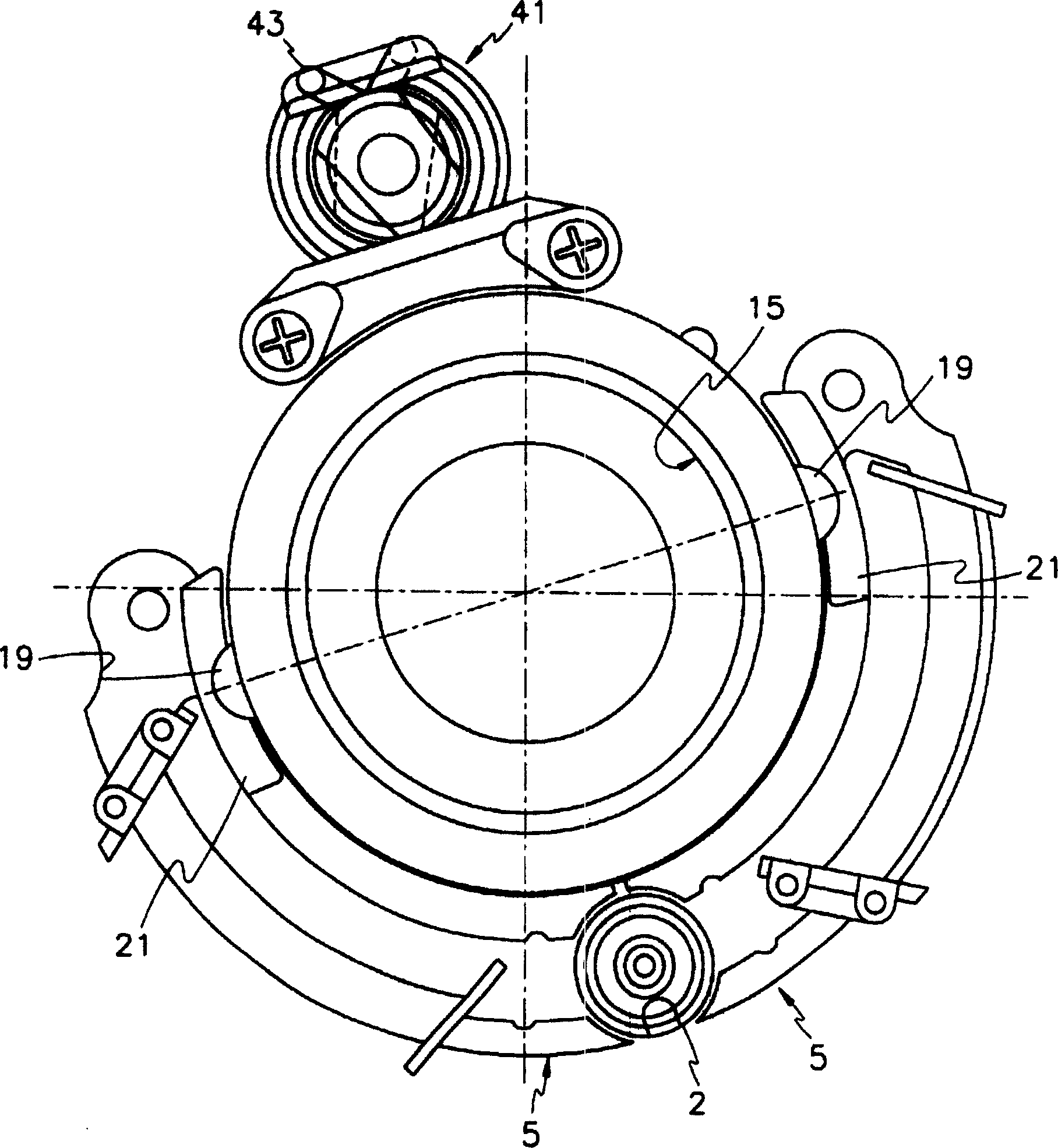
[0049] Reference numeral 1 in the figure denotes a power source, and the power source 1 functions as a part of the first driving section to drive the focus control ring 13 . The power supply 1 includes a rotor 2 , a motor gear 3 , and a pair of stators 5 . The rotor 2 is a permanent magnet with 4 poles. The motor gear 3 and the rotor 2 are integral structures. A pair of stators has four connection points ST 1 , ST 2 , ST 3 and ST 4 (See Image 6 ), the stepping pulse is added to the connection point in order to control the rotation direction of the motor and drive the rotor 2.

[0050] Each step pulse is applied to four connection points ST 1 , ST 2 , ST 3 and ST 4 , th...


PUM


Abstract

A method for driving a camera shutter, comprising, after the shutter is released for the first time, measuring the amount of light and the distance to the object, determining the focus position and exposure of the focus control lens on the object, reading out the focus compensation data stored in the memory, and calculating the compensation After the shutter is released for the second time, move the focus control lens to the compensated focus position to drive the shutter. The method for obtaining the focus compensation data includes: setting the focus control lens at the initial position; moving the lens barrel to the first zoom position of the object; measuring the actual focus lens position, and calculating the focus compensation distance; storing the calculated data into the record device.

Description

technical field [0001] The present invention relates to an electronic shutter for a camera, and more particularly to a driving method and device for an electronic shutter for a camera, wherein (a) the movement of the focus control lens required for focusing according to the distance of the object is minimized, thereby reducing the focus control time; (b) temperature variation during opening of the shutter is reduced, thus maintaining optimum exposure; (c) assembly defects are electronically compensated for reliable focus control throughout the entire focusing range. Background technique [0002] Cameras using electronic shutters generally have a system that implements automatic focus control by adjusting the focus control lens to match the distance between the camera and the object and completes automatic exposure by controlling the opening size of the aperture corresponding to the amount of light. [0003] Existing cameras utilizing such an electronic shutter are disclosed ...

Claims


Application Information

Patent Timeline
IPC IPC(8): G03B13/36G02B7/08G03B7/10G03B9/08G03B13/00
CPCG03B7/10G03B13/36G02B7/08G02B7/102H04N23/67
Inventor 徐在庆
Owner SAMSUNG ELECTRONICS CO LTD
Why Eureka
Try Eureka