
Contact connector system for light waveguides

A plug-in device and contact technology, which is applied in the coupling of optical waveguides, light guides, optics, etc., can solve the problems that cannot be used without problems, and the plug-in parts of the plug-in parts do not match.

Inactive Publication Date: 2005-08-03
REICHLE & DE-MASSARI
View PDF0 Cites 0 Cited by
  • Summary
  • Abstract
  • Description
  • Claims
  • Application Information

AI Technical Summary

Problems solved by technology

[0003] But the resulting problem is that this kind of plug-in parts cannot be used without any problem for most of the existing common molded electrical plug-in systems such as RJ45 or RJ11, because the cross-section of the plug-in parts Does not correspond to the plug-in interface of the electrical plug-in system

Method used


Image

  • Contact connector system for light waveguides
  • Contact connector system for light waveguides

Examples


Embodiment Construction

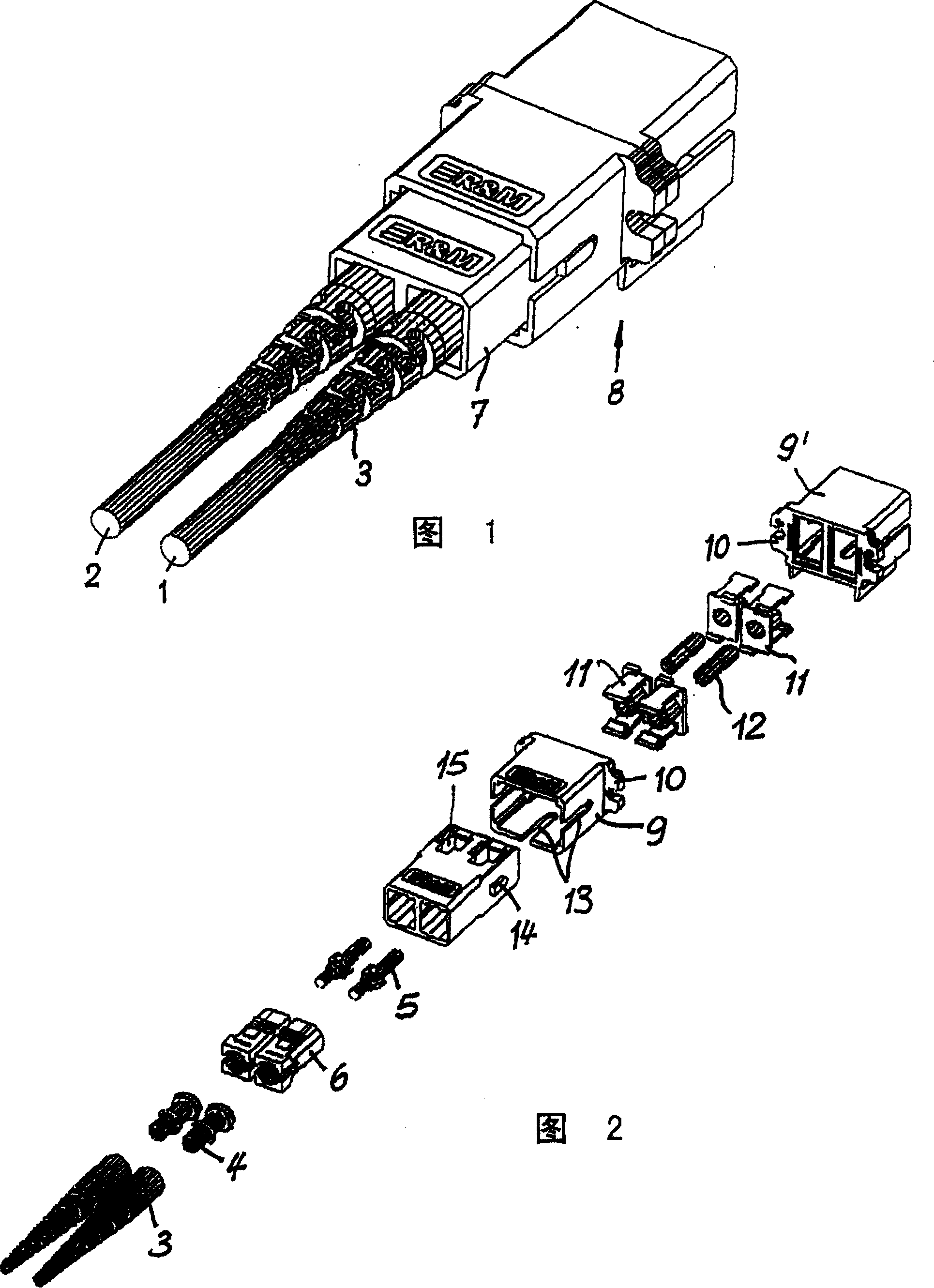
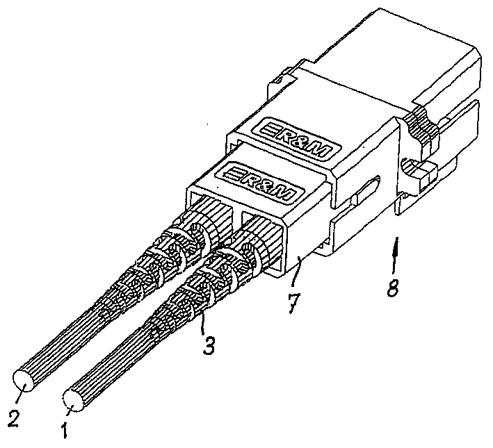
[0011] This embodiment is a contact plug-in device for two optical waveguides 1 and 2 that meets the requirements of the international standard connector SC. At the position, the terminal post and the end ferrule are wrapped by the connector 6.

[0012] The present invention is provided with accommodating at least two plug-in boxes 7 which are two plug connectors 6 in this embodiment, and the plug-in boxes 7 can be plugged in manually, and the plug-in boxes are connected to the given box through a coupler 8 of a suitable shape. International standard jacks (not shown) of a fixed electrical plug system such as RJ45 or RJ11 interact.

[0013] The coupler thus comprises two substantially identical packages 9, 9', which are connected to each other by means of a flange 10 or a socket or the like, and which contain contacting devices such as gates 11 and sockets. Barrel 12.

[0014] For this purpose, the encapsulation 9, 9' is designed to conform to the shape of the socket.

[00...


PUM


Abstract

The contact connector arrangement for optical waveguides of the internationally standardized SC connector whose connection ends are each formed by a male connector comprises a connector housing (7) which receives at least two male connectors (6), is used for the manual handling of the plug-in process and cooperates by way of coupling means (8) in a positive locking manner with predetermined plug-in openings of an electric connector system RJ 45 or RJ 11 or the like. This ensures that the connection ends of optical waveguides which are readily manufactured as male connectors can be used directly for modular electric connector systems such as RJ 45 or RJ 11.

Description

technical field [0001] The invention relates to a contact type plug-in device for optical waveguide meeting the requirements of the international standard plug-in device SC, the plug-in end of which is composed of plug-in parts. Background technique [0002] In order to insert, it is necessary to install a high-sensitivity connector for connection on the optical waveguide for manual operation. For this purpose, the optical waveguide is always terminated by means of an anti-crack element at the end ferrule and the terminal stud, which are enclosed by the plug connector. [0003] But the resulting problem is that this kind of plug-in parts cannot be used without any problem for most of the existing common molded electrical plug-in systems such as RJ45 or RJ11, because the cross-section of the plug-in parts Does not correspond to the plug-in interface of the electrical plug-in system. Contents of the invention [0004] Therefore, the object of the present invention is to pr...

Claims


Application Information

Patent Timeline
Patent Type & Authority Patents(China)
IPC IPC(8): G02B6/38
CPCG02B6/3893G02B6/3825G02B6/38
Inventor H·赖希勒
Owner REICHLE & DE-MASSARI
Learn More