
Card clothing for textile machine

A textile machine and card clothing technology, applied in textiles and papermaking, deburring devices, fiber processing, etc., can solve the problems of clogged and narrowed areas, impurity removal, and impurity wedges, etc.

Inactive Publication Date: 2005-08-17
STAEDTLER & UHL
View PDF0 Cites 0 Cited by
  • Summary
  • Abstract
  • Description
  • Claims
  • Application Information

AI Technical Summary

Problems solved by technology

[0004] However, this design has the disadvantage that impurities can accumulate and thus wedge or block the narrowed area, so that they cannot be removed despite cleaning operations, for example with high-pressure air

Method used


Image

  • Card clothing for textile machine
  • Card clothing for textile machine
  • Card clothing for textile machine

Examples


Embodiment Construction

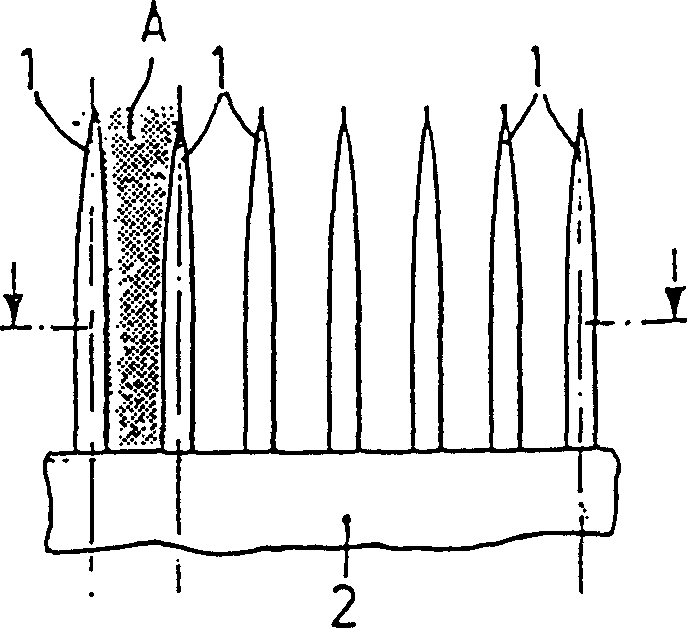
[0020] exist figure 1 In , a row of needles 1 is shown, which is fastened between two cover plates 2 while forming a needle strip.

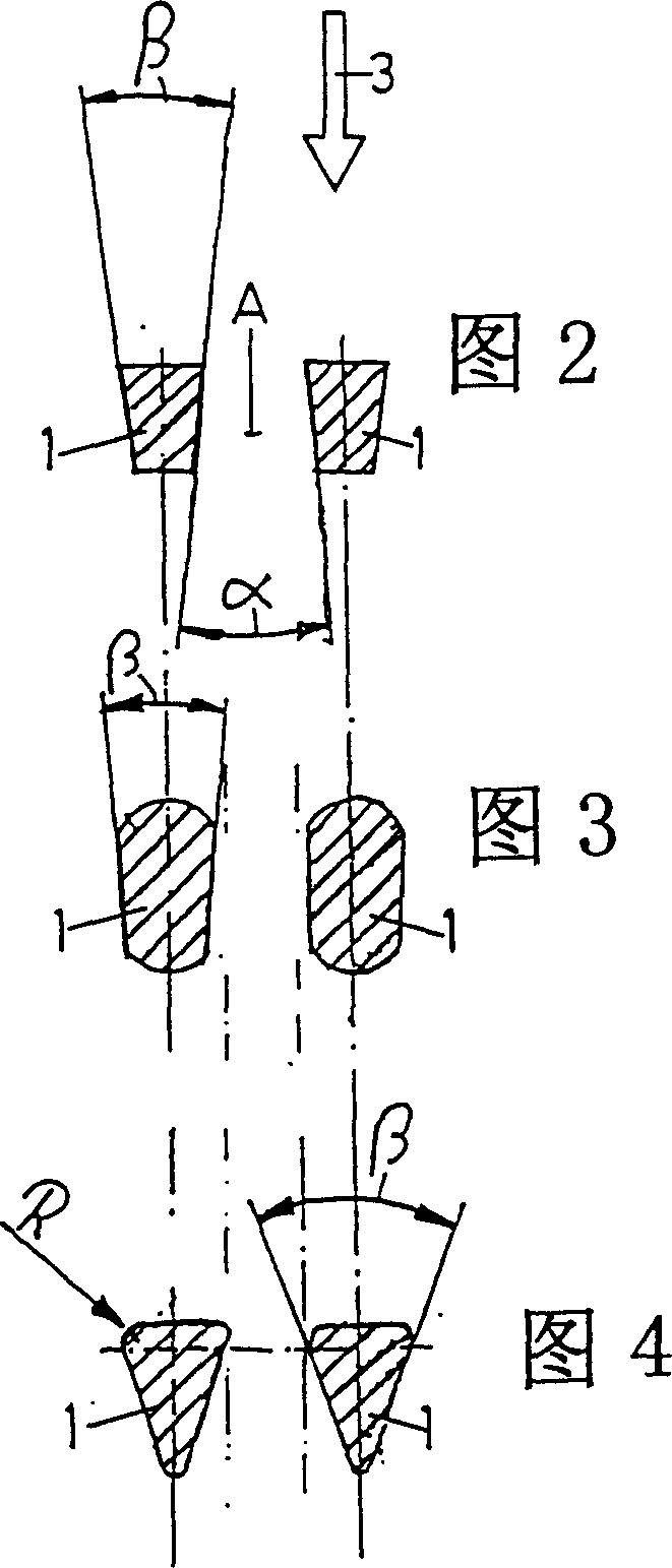
[0021] The needles 1 are arranged between two cover plates 2, these needles are parallel to each other and have a certain distance apart, so just leave a free passage area A between every two needles 1, through this free passage, the comb to be combed bar in Figure 2 to Figure 6 Move in the direction of the arrow 3 drawn on it.

[0022] In the embodiment of FIG. 2 , the needles 1 have a completely trapezoidal cross-section, so that the free passage area A expands steadily at an angle α between the needles 1 in the direction of movement of the sliver (arrow 3 ).

[0023] In the exemplary embodiment of FIG. 3 , the needles likewise have a trapezoidal basic shape, however, their ends are rounded and the needles taper accordingly at an angle β in the direction of movement (arrow 3 ).

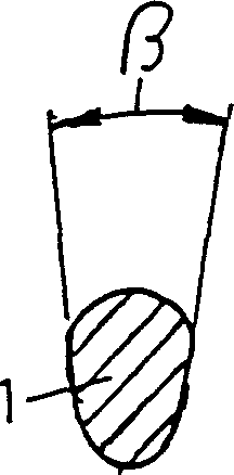
[0024] In the embodiment of FIG. 4 , the cross-section of the...


PUM


Abstract

In card clothing for a textile machine comprising a plurality of adjacent spaced-apart needles or serrated punched cut-outs disposed in rows, wherein the needles or serrated punched cut-outs are stamped and accordingly have a non-rectangular cross-sectional geometry, wherein a free passage zone for the fibers being combed is formed between the spaced-apart needles or serrated punched cut-outs, it is provided that the free passage zone (A) steadily widens viewed in the direction of travel of the sliver.

Description

technical field [0001] The invention relates to a card clothing for a textile machine, comprising a plurality of needles or zigzag stampings arranged side by side at a distance from one another, wherein the needles or zigzag stampings are pressed and respectively have a non-rectangular cross-section Geometry in which one free passage for the fibers to be carded is formed between needles or zigzag punches spaced apart from each other. Background technique [0002] This type of clothing is used in various types of textile machines, such as circular combs, top combs, cards, etc. In this connection, it is known to use pressing, that is to say cold forming, to shape at least partially the tip of a needle or sawtooth stamping in order to change the original circular or rectangular cross-sectional shape. [0003] For example, in the case of needles, it is known to adopt a rhomboid cross-sectional profile, so that, seen in the direction of movement between the sliver and the needle...

Claims


Application Information

Patent Timeline
Patent Type & Authority Patents(China)
IPC IPC(8): D01G15/86D01G15/88
CPCD01G15/88
Inventor 弗莱德里希·亨宁格
Owner STAEDTLER & UHL
Learn More