Biochip detecting system

A biochip, detection system technology, applied in biological testing, microbial determination/inspection, biochemical equipment and methods, etc. High collection efficiency

Inactive Publication Date: 2005-10-19
INST OF OPTICS & ELECTRONICS - CHINESE ACAD OF SCI
View PDF0 Cites 1 Cited by
  • Summary
  • Abstract
  • Description
  • Claims
  • Application Information

AI Technical Summary

Problems solved by technology

The above two instruments are mainly for the detection of high-density gene chips, and the equipment is complicated and expensive

Method used


Image

  • Biochip detecting system
  • Biochip detecting system
  • Biochip detecting system

Examples


Embodiment Construction

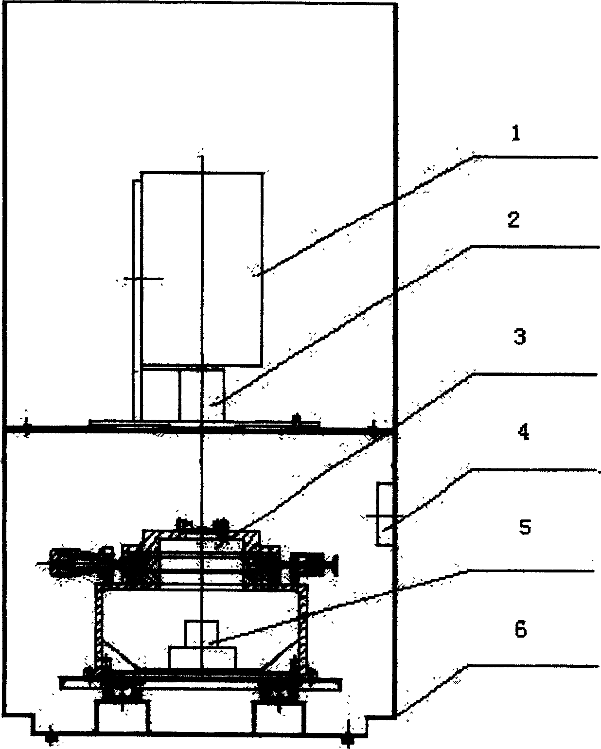
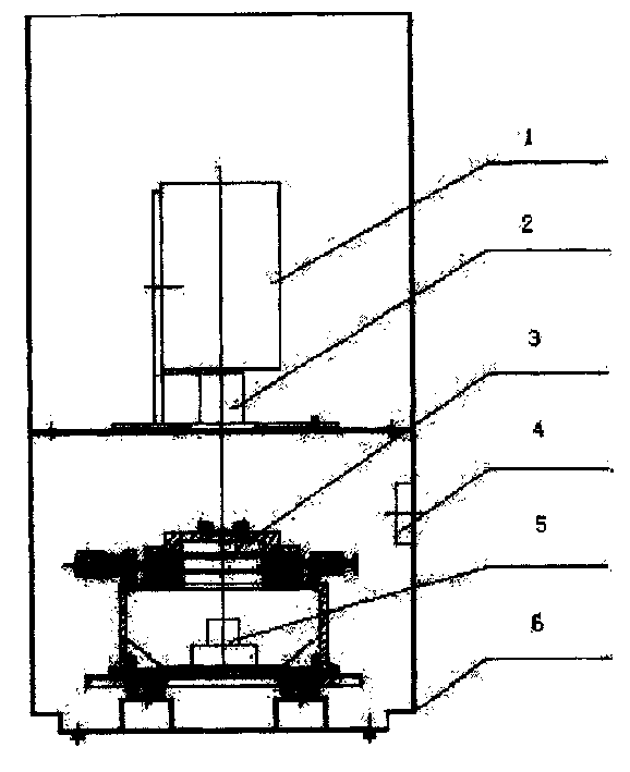
[0015] Such as figure 1 As shown, the present invention is made up of 12 semiconductor cooling CCD camera 1, high-efficiency objective lens 2, X-Y two-dimensional table 3, barcode inspection head 4, incandescent lamp 5, black box 6, computer, and the mark that needs to detect has chemical The luminous biochip is first scanned on the barcode detection head 4, and the computer registers the sample by identifying it, and then puts the sample on the X-Y two-dimensional stage 3, adjusts the X-Y two-dimensional stage 3 so that the sample is in the center of the objective lens 2, and places the dark box 6 The door is closed, the sample is in the dark box, and the CCD parameters, such as exposure time, resolution, etc., are set by executing software on the computer, and then the chemiluminescent image can be collected. The chemiluminescent signal on the sample is captured by the objective lens 2 and imaged on the CCD camera 1, and then the computer undergoes image processing and image...


PUM

PropertyMeasurementUnit
lengthaaaaaaaaaa

Abstract

The invention is a biochip detecting system, composed of semiconductor cooling CCD camera, high-efficiency object lens, X-Y 2-D table, bar code detect-read head, filament lamp, camera bellows, and computer. Use the bar code detect-read head to scan the biochip with chemical luminescence label, make the computer resister by identifying sample, then place the sample on the X-Y planar table, adjust the planar table to make the sample at the center of the object lens, close the door of the camera obscura to make the sample in the camera obscura, image the chemical luminescence signal on the CCD camera, and set the CCD parameters by software in the computer, like time of exposure, resolution, etc, to start collecting the chemical luminescence image.

Description

Technical field [0001] The invention relates to a biological chip detection system. Background technique [0002] Gene chips and protein chips are biochips used to detect the expression levels of multiple genes or proteins at the same time, and will become the most important molecular diagnostic means in this century. In the fields of health care, drug screening, environmental protection, agriculture, public security, settlement of civil disputes, and epidemic prevention. [0003] At present, the instruments used for biochip detection on the market are mainly divided into laser scanning type and CCD type. Among them, American Axon, Packand and Affymetrix companies have launched laser scanning type gene chip detectors, which generally have more than two lasers. , to obtain an image of the entire chip by spot scanning. Moreover, in order to prevent high errors caused by high density, high-density gene chips all use simultaneous hybridization of equal amounts of samples and r...

Claims


Application Information

Patent Timeline
Patent Type & Authority Patents(China)
IPC IPC(8): C12Q1/68G01N21/62G01N33/48
Inventor 岑辉唐小萍刘业异王淑蓉邢薇张强
Owner INST OF OPTICS & ELECTRONICS - CHINESE ACAD OF SCI
Why Eureka
Try Eureka