Biochip Scanner Fluorescence Collection Objectives

A biochip and scanner technology, applied in fluorescence/phosphorescence, optics, instruments, etc., can solve the problems of small selection range of fluorescent reagents, non-uniform imaging, small back intercept of lens, etc. Long, the effect of improving the detection sensitivity

Active Publication Date: 2015-12-02
无锡国盛生物工程股份有限公司
View PDF7 Cites 0 Cited by
  • Summary
  • Abstract
  • Description
  • Claims
  • Application Information

AI Technical Summary

Problems solved by technology

But this lens also has the following disadvantages: (1) The length of this lens is too long; (2) The imaging of each field of view is not very uniform; (3) The back focus of the lens is small; (4) The selection range of fluorescent reagents is small
[0005] Another example is the Chinese patent publication CN1657913A disclosed on August 24, 2005, titled "Microarray Chip Detection System". The disclosed microarray chip detection system adopts the method of CCD imaging. The system uses 12 lenses and has a complex structure.

Method used


Image

  • Biochip Scanner Fluorescence Collection Objectives
  • Biochip Scanner Fluorescence Collection Objectives
  • Biochip Scanner Fluorescence Collection Objectives

Examples


Embodiment Construction

[0019] Now in conjunction with the accompanying drawings, the fluorescence detection objective lens will be further described in detail.

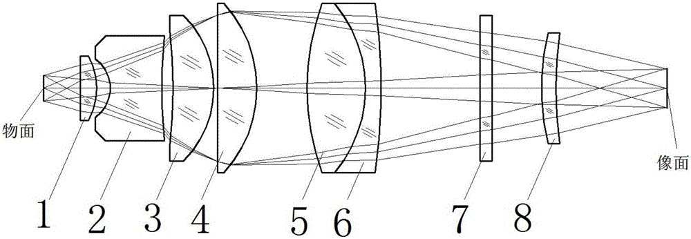
[0020] Such as figure 1 As shown, the fluorescence collecting lens of the present invention includes sequentially from the object side to the image side along the optical axis: a biochip scanner fluorescence collecting objective lens, including 8 lenses, from the object side to the CCD imaging surface, and the fluorescence signals pass through in sequence: J1 Plano-convex positive lens 1, J2 double-concave negative lens 2, J3 concave-convex positive lens 3, J4 plano-convex positive lens 4, J5 bi-convex positive lens 5, J6 concave-convex negative lens 6, J7 plano-planar lens 7, J8 convex-concave positive lens 8, Each lens is arranged on an optical axis, wherein J5 double-convex positive lens 5, J6 concave-convex negative lens 6 form a doublet lens, and an aperture stop is set on the surface near the object side of J4 plano-convex positive le...


PUM


Abstract

The invention relates to a fluorescence collecting object lens of a biological chip scanner, which is based on a CCD or CMOS imaging method. The fluorescence collecting object lens comprises eight lenses, and fluorescence signals successively penetrate through a plano-convex positive lens J1, a double-concave negative lens J2, a concave-convex positive lens J3, a plano-concave positive lens J4, a plano-convex positive lens J5, a concave-convex negative lens J6, a plano-plane lens J7 and a convex-concave positive lens J8 from an object side to a CCD imaging surface, wherein the lenses are arranged on a optical axis, the double-convex positive lens J5 and the concave-convex negative lens J6 form a double gummed lens, an aperture diaphragm is arranged on the surface of the plano-convex positive lens J4 close to the object side, and the plano-plane lens J7 is an optical filter of emission fluorescence. The fluorescence collecting object lens of the biological chip scanner provided by the invention is simple in structure, low in cost, and large in view field, can rapidly increase scanning speed, substantially improves the fluorescence collection efficiency and detection flexibility, and can be suitable for all visible optical bands.

Description

technical field [0001] The invention relates to a fluorescence detection optical imaging objective lens, in particular to a fluorescence collection objective lens applied to a biological chip scanner based on a CCD or CMOS imaging method. Background technique [0002] At present, most of the biochip scanners use fluorescent dyes to label, use strong excitation light to irradiate the biochip to excite the fluorescence signal, and use the detector to detect the fluorescence intensity to obtain the information of the biochip, and then obtain valuable biological information through analysis software processing. [0003] For the fluorescence scanning system detected by the CCD imaging principle, the performance of the fluorescence collecting objective lens plays a key role in the quality of the detection equipment. Several important indicators of the imaging lens: (1) the numerical aperture of the lens, use a large value The aperture objective lens can significantly improve the f...

Claims


Application Information

Patent Timeline
Patent Type & Authority Patents(China)
IPC IPC(8): G02B13/00G01N21/64
Inventor 王振宇马贵兰戴良
Owner 无锡国盛生物工程股份有限公司
Why Eureka
Try Eureka