A flow-through fluorescence detection cell

A fluorescence detection and detection cell technology, applied in the field of fluorescence detectors, can solve problems such as high background noise of detection cells, and achieve the effects of reducing high background noise, wide inner diameter range, and simple device

Active Publication Date: 2017-06-16
DALIAN INST OF CHEM PHYSICS CHINESE ACAD OF SCI
View PDF6 Cites 0 Cited by
  • Summary
  • Abstract
  • Description
  • Claims
  • Application Information

AI Technical Summary

Problems solved by technology

[0004] In order to improve the deficiencies of the prior art, the present invention provides a novel flow-through fluorescence detection cell, which effectively solves the problem of high background noise in the existing detection cell

Method used


Image

  • A flow-through fluorescence detection cell
  • A flow-through fluorescence detection cell

Examples


Embodiment 1

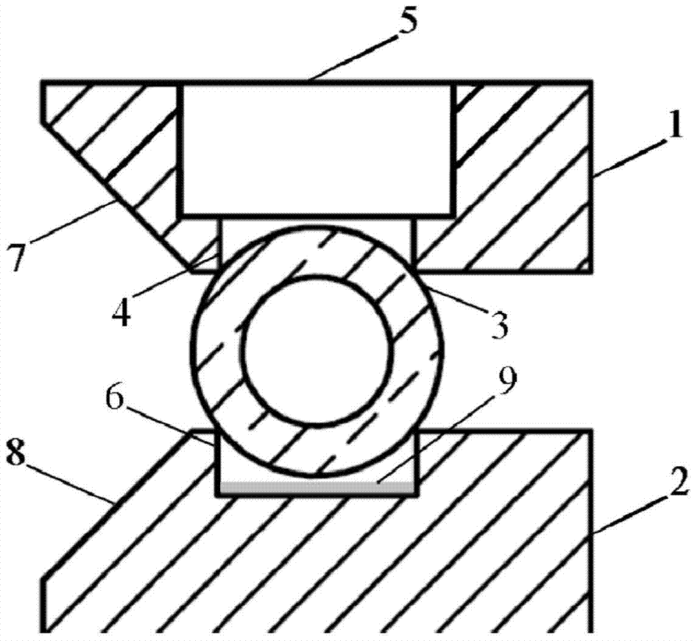
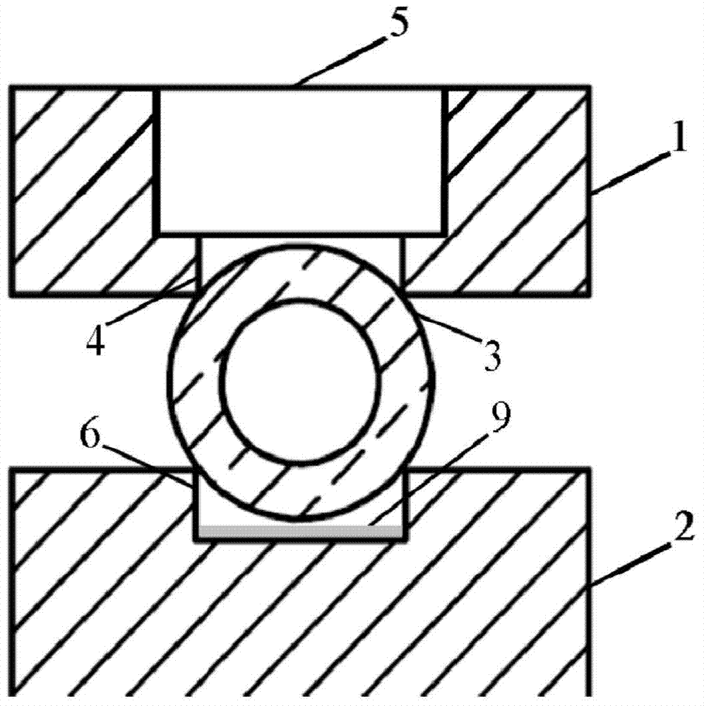
[0034] A flow-through fluorescent detection cell, the cross-sectional view is as follows figure 1As shown, it consists of an upper clamp 1, a lower clamp 2 and a cylindrical quartz tube 3. The upper clamp 1 and the lower clamp 2 are oxidized and blackened aluminum materials. The upper clamp 1 is a cylindrical structure, and the lower end surface is provided with a through rectangular upper groove 4; at the bottom of the rectangular upper groove 4, the upper end surface of the clamp 1 is vertically upwardly provided with a through hole as a light hole 5, The depth of the light hole 5 reaches the bottom of the upper groove 4; the lower clamp 3 is a cylindrical structure, and the top is provided with a rectangular lower groove 6; the bottom of the lower groove 6 is provided with a reflector 9, and the reflector 9 is aluminum membrane. The quartz tube 3 has an inner diameter of 3 mm and an outer diameter of 5 mm, and is clamped between the upper groove 4 and the lower groove 6 a...

Embodiment 2

[0042] For the fluorescence detection cell described in Example 1, the excitation optical path is changed to an excitation optical fiber with a core diameter of 5 mm, the excitation optical fiber is inserted into the light hole 5, and the emitted light is irradiated onto the quartz tube 3 through the excitation optical fiber. The fluorescence collection optical path is changed to a 3mm fluorescence collection optical fiber; the fluorescence collection optical fiber is inserted into the gap between the upper clamp 1 and the lower clamp 2, and its axis is perpendicular to the axis of the quartz tube 3; both the excitation optical fiber and the fluorescence collection optical fiber are physically connected to the quartz tube touch.

[0043] The experimental results are: Compared with the existing close-fitting detection pool (Talanta, 2012, 88, 463-467), the detection signal-to-noise ratio is increased by 2.5 times.

Embodiment 3

[0045] Fluorescence detection cell as described in Example 1, wherein the quartz tube 3 is changed to a quartz capillary with an inner diameter of 50 microns and an outer diameter of 365 microns; the width of the upper groove 4 and the lower groove 6 is 0.2 mm, and the depth is 0.1 mm.


PUM


Abstract

The invention provides a flow-through fluorescent detection pool, which is composed of an upper clamp, a lower clamp and a quartz tube. The upper clamping part has a cylindrical structure, the lower end surface is provided with a through rectangular upper groove, and the upper end face is vertically provided with a light hole; the top of the lower clamping part is provided with a penetrating rectangular lower groove; the quartz tube is clamped in the flow cell Between the upper groove and the lower groove, the penetrating directions of the upper groove and the lower groove are parallel to the axial direction of the quartz tube. When the light source is irradiated onto the quartz tube through the hole, the strong reflected excitation light generated by the optical interface on the outer surface of the air-quartz tube is blocked by the two inner edges of the upper groove, and cannot be transmitted into the fluorescence collection optical path, thus effectively weakening the reflected excitation light The resulting high background noise improves the detection signal-to-noise ratio. The detection cell has a simple structure and is easy to manufacture, and is suitable for capillary electrophoresis, liquid chromatography and flow analysis fluorescence detectors.

Description

technical field [0001] The patent of the present invention relates to the technical field of fluorescence detectors, more specifically, to a flow-through fluorescence detection cell. Background technique [0002] Liquid chromatography and capillary electrophoresis, as high-efficiency separation techniques, are widely used in the separation and analysis of mixed substances. Fluorescence detector (FLD) is a highly sensitive and highly selective detector, combined with liquid chromatography, capillary electrophoresis and fluorescence detector, widely used to detect complex mixed trace biological and environmental substances. The detection cell is one of the core components of the fluorescence detector, and the design of the detection cell directly affects the performance of the entire detection system. Researchers usually design the detection cell according to the designed excitation and emission light path structure. There are generally three ways to focus or collect the exc...

Claims


Application Information

Patent Timeline
Patent Type & Authority Patents(China)
IPC IPC(8): G01N21/64G01N21/01
Inventor 关亚风耿旭辉刘洪鹏完玲中
Owner DALIAN INST OF CHEM PHYSICS CHINESE ACAD OF SCI
Why Eureka
Try Eureka