Locomotive gear wheel box and its production method

A technology for gearboxes and locomotives, which is applied to transmissions driven by electric motors, transmissions with rotating prime movers, etc., can solve problems such as oil leakage and easy cracking, and achieve high interchangeability, reduced box weight, The effect of reduced strength requirements

Inactive Publication Date: 2005-10-26
刘吉祥
View PDF0 Cites 2 Cited by
  • Summary
  • Abstract
  • Description
  • Claims
  • Application Information

AI Technical Summary

Problems solved by technology

[0003] In order to overcome the shortage of oil leakage caused by the welded seam of the existing welded gearbox, the present invention provides a locomotive gearbox with no welded seam at the oil-filling part and its manufacturing method

Method used


Image

  • Locomotive gear wheel box and its production method
  • Locomotive gear wheel box and its production method
  • Locomotive gear wheel box and its production method

Examples


Embodiment Construction

[0022] The manufacture method of locomotive gear box of the present invention comprises following processing steps:

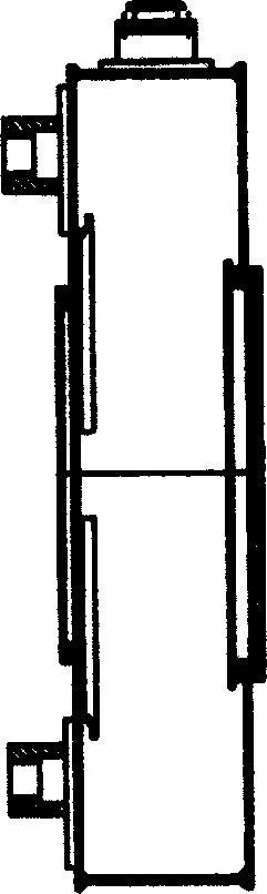
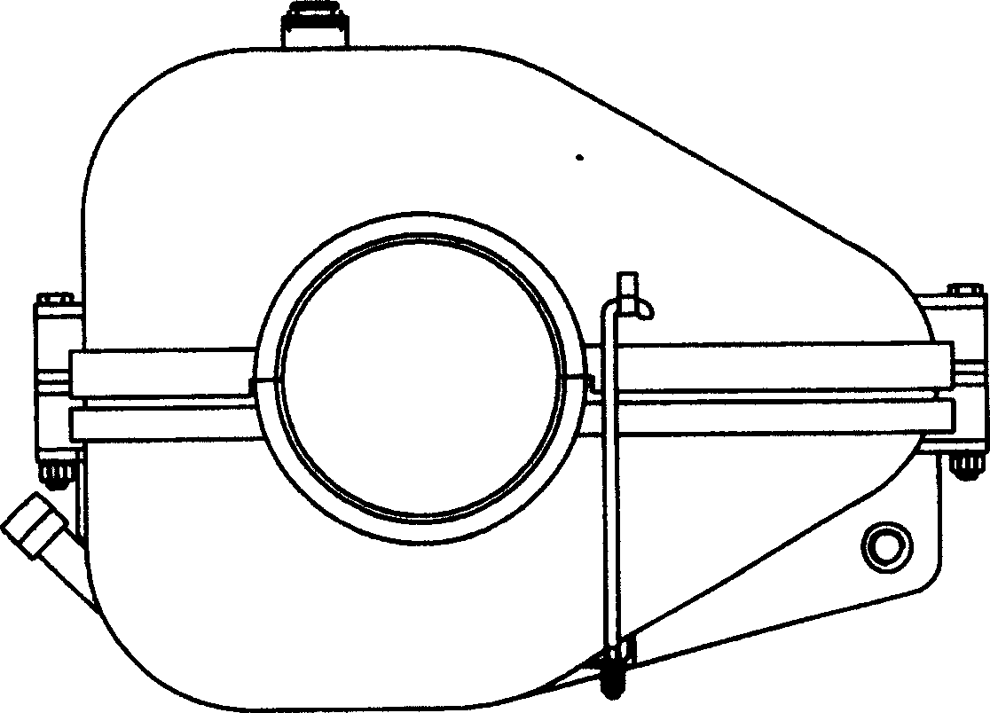
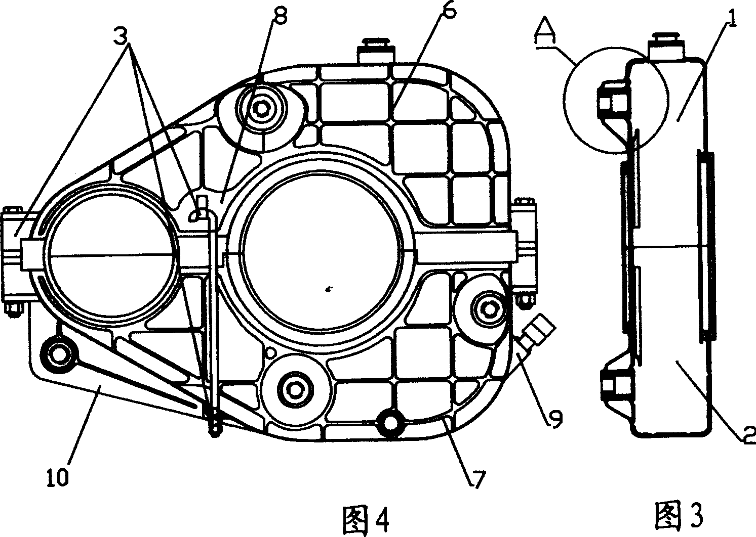
[0023] The 2-5mm steel plate that has been blanked, preferably 2-3mm steel plate, is cold-stretched or hot-stretched multiple times to form the box profile of the upper cover 1 and the lower cover 2; Reinforcing ribs 6, reinforcing ribs 7, and hanging welding bosses 8 are formed on the surface of the box body; and then through multiple cold pressing and punching to form oil standard seat welding bosses 9; and then through multiple punching, flanging, and pressing , forming the upper cover interface flange 11, the lower cover interface flange 12 and the seam 4 for installing the sealing strip 5, the seam 4 can also be formed by welding after being made separately; then the upper cover 1, the lower cover 2 and the The reinforcing support rib 13 formed by cold pressing for many times and the coupling nut welding boss 10 formed by cold pressing for many times, the ...


PUM


Abstract

A gear box for locmotive is composed of an upper cap, a lower cap and a joint part. The upper and lower caps are made up of 2-3 mm thick steel plate through cold and hot stretching several times. Their peripheral edges have the reinforcing rib formed by cold pressing several times. The circular or shaped reinforcing ribs are also made at the positions where local reinforcing is needed. Its advantages are reduced thickness of steel plate, no welded seam, high strength, and light weight.

Description

technical field [0001] The invention relates to a gear box and a manufacturing method thereof, in particular to a locomotive gear box used on a train locomotive and a manufacturing method thereof. Background technique [0002] Electric locomotives, diesel locomotives, light rail trains and subway trains all use traction motors to drive the wheels to rotate through the gear transmission in the gearbox, that is, to drive the train. At present, the traditional locomotive gearbox is welded with 5-6mm steel plates, which is not only heavy, but also due to welding defects, uneven welding stress, impact when the locomotive passes through rail gaps and turnouts at high speed, and changes in temperature. All may cause the casing weld to crack, thereby causing the oil leakage of the gearbox and affecting the normal operation of the train, which not only causes economic losses, but also causes environmental pollution near the railway. Contents of the invention [0003] In order to o...

Claims


Application Information

Patent Timeline
Patent Type & Authority Patents(China)
IPC IPC(8): B61C9/32B61C9/48
Inventor 刘吉祥
Owner 刘吉祥
Why Eureka
Try Eureka