Connector for printed circuit board

A technology for printed circuit boards and connectors, applied in the field of connectors, can solve the problems of increasing manufacturing costs, increasing the number of components, and complex inventory control.

Inactive Publication Date: 2005-11-23
JST MFG CO LTD
View PDF0 Cites 0 Cited by
  • Summary
  • Abstract
  • Description
  • Claims
  • Application Information

AI Technical Summary

Problems solved by technology

This not only increases manufacturing costs but also increases the number of constituent parts, significantly complicating their inventory control

Method used


Image

  • Connector for printed circuit board
  • Connector for printed circuit board
  • Connector for printed circuit board

Examples


Embodiment Construction

[0032] Some preferred embodiments of the invention will now be described with reference to the accompanying drawings.

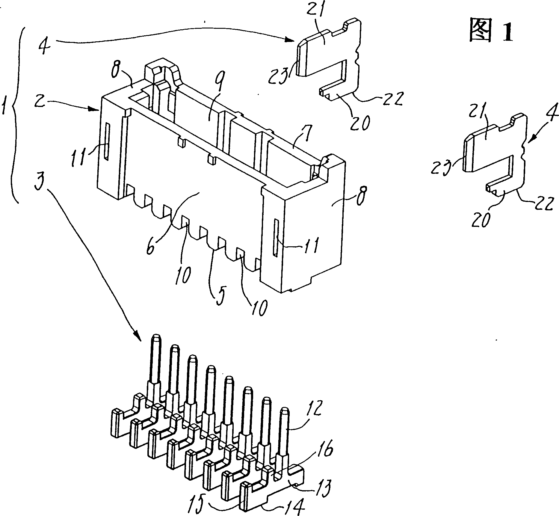
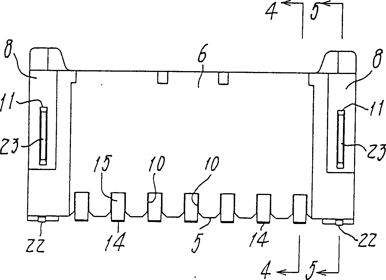
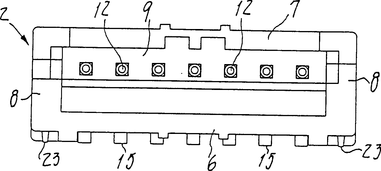
[0033] 1 to 5 show a connector 1 provided here as a plug for a printed circuit board. The connector 1 has an insulating shell 2, a row of contacts 3 kept at a regular interval in the shell, and reinforcing metal sheets 4 fixed on both sides of the shell.

[0034] The casing 2 is an elongated box made of insulating material and has an opening facing upward. The opening in the box is defined between the bottom 5 , the front wall 6 , the rear wall 7 and the opposite side walls 8 and 8 . The open top 9 of the housing serves as a spout for a mating connector (not shown). Slot-shaped cutouts 10 are formed in the bottom 5 at constant intervals to engage with the contacts 3 respectively. Apertures 11 and 11 are formed in the side wall 8 to receive and fixedly retain the respective reinforcement metal 4 therein.

[0035] The contacts 3 are manufactured by punching...


PUM


Abstract

A connector (1) for printed circuit boards (25) has an insulated housing (2), contacts (3) each with a lead (13) protruding from the contact to be soldered to a circuit pattern (26), and reinforcement metals (4) fixed in both sides of the housing and capable of soldering to a fixation pattern (27) on a board. These housing (2), contacts (3) and metals (4) are useful as they are, whether the connector takes a top type or a side type position. Each lead (13) and metal (4) respectively have first solderable portion (14) and zone (22) for top type position, and second solderable portion (15) and zone (23) for the side type position. The first portions and zones extend along the housing's bottom (5), the second portions and zones extending along the housing's front wall (6) or rear wall (7), such that the housing, contacts and metals need no change in shape between the top type and side type position so that the connector is made efficiently with reduced facility investment and with reduced sorts of its parts, lowering manufacture cost and facilitating stock control of parts.

Description

technical field [0001] The invention relates to a connector suitable for and surface mounted on a printed circuit board. Background technique [0002] Such known connectors for printed circuit boards each comprise a rectangular box as an insulating housing. The latter usually has an open upper connection portion for receiving conductive parts or elements leading to the circuit board. Leads integral with the contacts held in the housing project outwardly therefrom to be soldered to a circuit pattern printed on the board. The reinforcement metal sheets fixed in both sides of the housing will be soldered to a fixed pattern pre-formed on each printed circuit board. These prior art connectors are divided into so-called "top" types and so-called "side" types. In the former type, the bottom of the housing will be placed on top of the printed circuit board so that the connecting portion opens upward. In the latter type of connector, the front or rear side of the housing will rest...

Claims


Application Information

Patent Timeline
Patent Type & Authority Patents(China)
IPC IPC(8): H01R12/71H01R12/57H01R13/66
CPCH01R12/57E03D9/052A47K13/307F24F7/06E03D11/02
Inventor 藤木昭彦后丰正木克之
Owner JST MFG CO LTD
Why Eureka
Try Eureka