
Combination oil-well pump

An oil pump and sucker rod technology, which is applied in the field of combined oil pumps, can solve problems such as restrictions and achieve the effect of increasing the liquid discharge.

Inactive Publication Date: 2006-02-01
PETROCHINA CO LTD
View PDF0 Cites 0 Cited by
  • Summary
  • Abstract
  • Description
  • Claims
  • Application Information

AI Technical Summary

Problems solved by technology

After the pump diameter is enlarged, the sucker rod and the pumping unit will bear greater force when the pump plunger is lifted up, which limits the expansion of the pump diameter.

Method used


Image

  • Combination oil-well pump
  • Combination oil-well pump
  • Combination oil-well pump

Examples


Embodiment 2

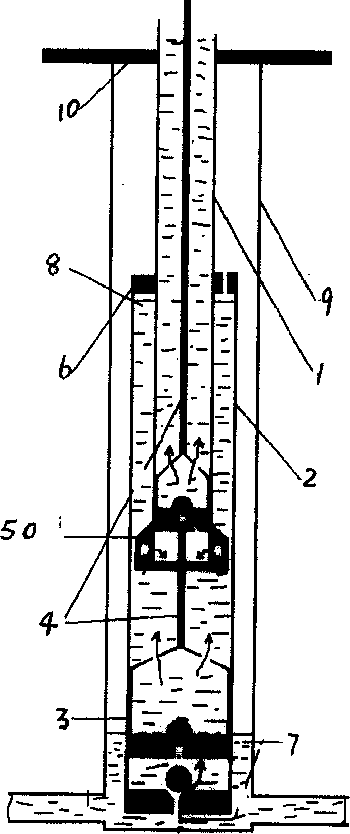
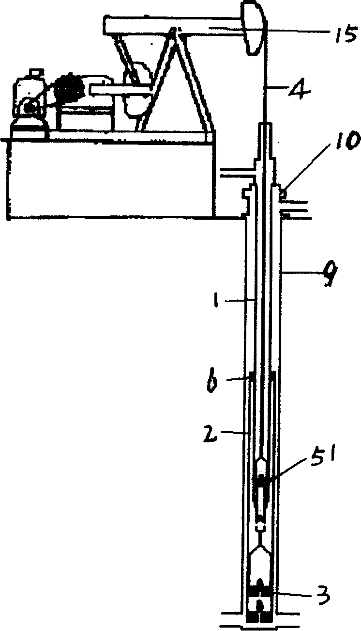
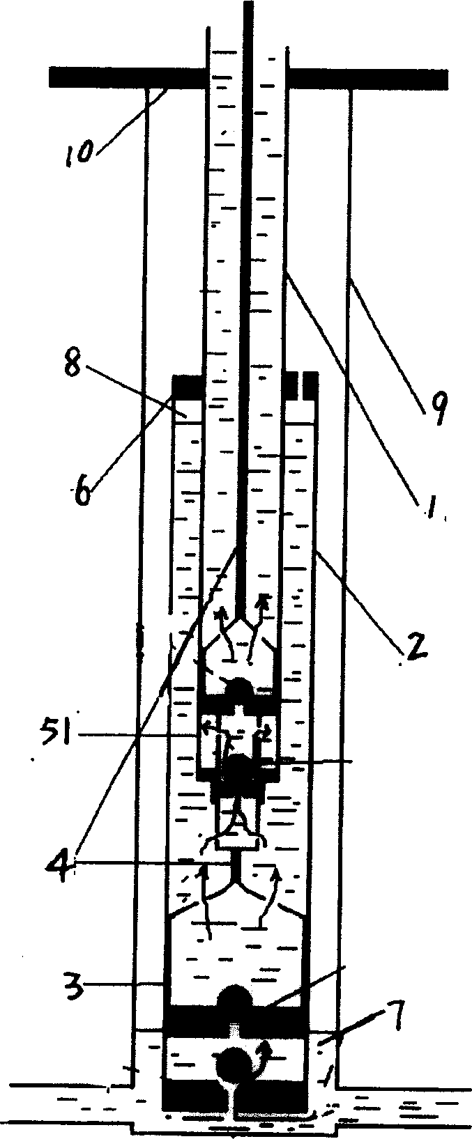
[0020] Such as 2, Figure 4 As shown, the combined pump consists of a large-diameter pump 3, a small-diameter hydraulic feedback pump 51, a small tubing 1, a large tubing 2, a tubing holder 6, a casing 9, a wellhead 10, a sucker rod 4, and a pumping unit 15 It is composed of necessary equipment for oil production. Casing pipe 9 has an inner diameter of 140 millimeters; large oil pipe 2 has an inner diameter of 100 millimeters and a length of 300 meters; and small oil pipe 1 has an inner diameter of 63.5 millimeters. The small-diameter hydraulic feedback oil well pump 51 is fixed on the bottom of the small oil pipe 1 . The small oil pipe 1 is inserted into the large oil pipe 2 from the oil pipe holder 6 at the top of the large oil pipe 2 , and extends downward to connect with the upper part of the small-diameter hydraulic feedback oil well pump 51 . In the small-diameter hydraulic feedback oil well pump 51 , the lower end of the sucker rod 4 is connected to the plunger top of...


PUM


Abstract

The combined oil pump for extracting oil includes large diameter oil pump, small-diameter annular valve type oil pump, oil pipe fixer, oil pumping rod, etc. The small-diameter annular valve type oil pump is connected with small oil pipe and its plunger is connected to the oil pumping rod, and the other end of the oil pumping rod is connected to the plunger of the large diameter oil pump. The liquid is pumped with the large oil pump to the annular space between the large and the oil pipes to form the second liquid surface, and the second surface has greater submergence depth than the natural oil deposit. The small pump has sucking port submerged inside the great submergence depth to pump the liquid to ground. The oil pumping rod and the oil pumping machine can bear the force produced by the small pump in raising the plunger, and the present invention can raise the liquid pumping amount in relatively low submergence depth.

Description

[0001] Involved areas [0002] The invention relates to a combined oil well pump in oil production engineering. Background technique [0003] When using an oil well pump for oil extraction, the submergence of the pump has a great relationship with the filling degree and pump efficiency of the pump. When the reservoir pressure is low, the natural sinking degree is very small, and the filling degree of the pump is also very small. In order to increase the displacement of the pump, the usual method is to enlarge the diameter of the pump. After enlarging the pump diameter, the sucker rod and the pumping unit will bear greater force when the pump plunger is lifted up, which limits the expansion of the pump diameter. Contents of the invention [0004] The purpose of the present invention is to provide a combination of a large-diameter pump and a small-diameter pump, which solves the process of lifting the liquid from the large pump to the surface by the small pump, thereby realiz...

Claims


Application Information

Patent Timeline
Patent Type & Authority Patents(China)
IPC IPC(8): F04B47/02F04B3/00E21B43/00
Inventor 陈亚平张义堂石玉鹏常毓文李松林王东辉宋龙王春雨韩静
Owner PETROCHINA CO LTD
Learn More