
Apparatus for bending cutting blade to precisley form acute angle

A technology of cutting blades and bending devices, which is applied in the direction of knives, forming tools, applications, etc., and can solve problems such as complex device control

Inactive Publication Date: 2006-02-08
朴 洪顺
View PDF0 Cites 0 Cited by
  • Summary
  • Abstract
  • Description
  • Claims
  • Application Information

AI Technical Summary

Problems solved by technology

However, the problem with this common cutting blade bending device is that the acute angle at which the cutting blade 100 can be bent is limited to a certain value.
But this device still has a weak point, in order to bend the metal strip counterclockwise, the rotating body must rotate a large angle clockwise, so it is difficult to reserve a large space between the guide part and the metal strip bending part, so that this The control of the device becomes complicated
[0006] In addition, although this device is advanced compared to the aforementioned cutting blade bending device in terms of sharp-angle forming capability, since a single bending part sequentially bends the metal strip in two directions, considering the operation Compared with the cutting blade bending device mentioned above, it is not necessarily appropriate to say that this device is advanced

Method used


Image

  • Apparatus for bending cutting blade to precisley form acute angle
  • Apparatus for bending cutting blade to precisley form acute angle
  • Apparatus for bending cutting blade to precisley form acute angle

Examples


Embodiment Construction

[0026] Preferred embodiments of the invention are described in more detail below, one of which is illustrated in the accompanying drawings. Where possible, the same reference numbers are used throughout the figures and descriptions for the same or like parts.

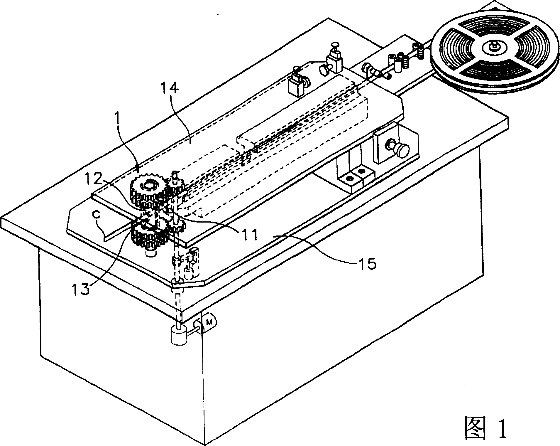
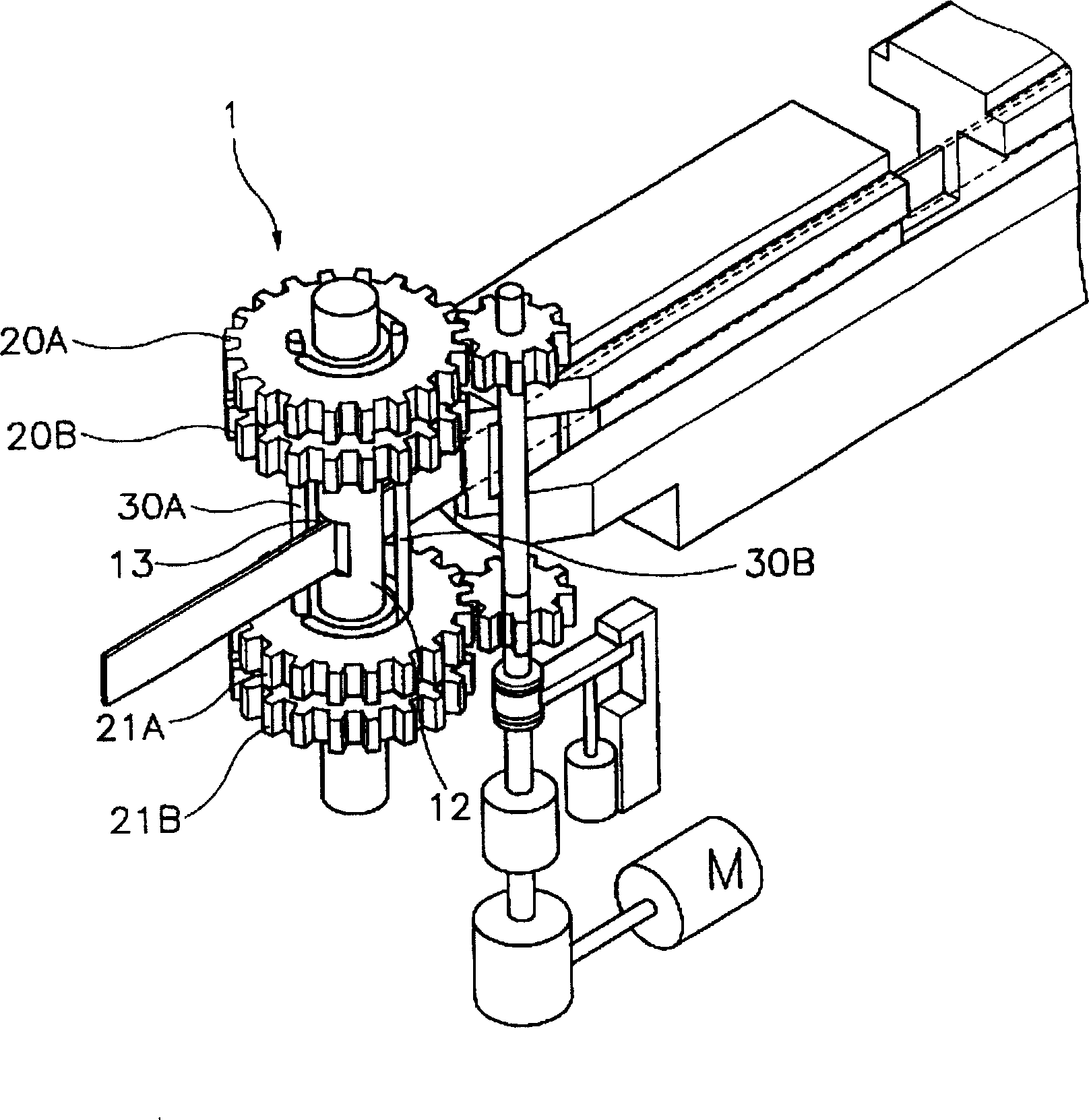
[0027] Referring to Fig. 1, it shows a schematic perspective view of the overall structure of the bending system including the bending device 1 of the present invention; except for the bending device 1 at the front of the bending system, the structure of the entire bending system of the present invention is the same as that of the present application The same as described in the USP6,145,359 of people. A nozzle portion 12 for feeding the cutting blade C into the bending area is installed in front of the guide portion 11 . The nozzle part 12 feeds the cutting blade C coming from the guide part 11, passes through the guide opening 13 provided along the length direction of the cutting blade, and reaches the bending area.

...


PUM


Abstract

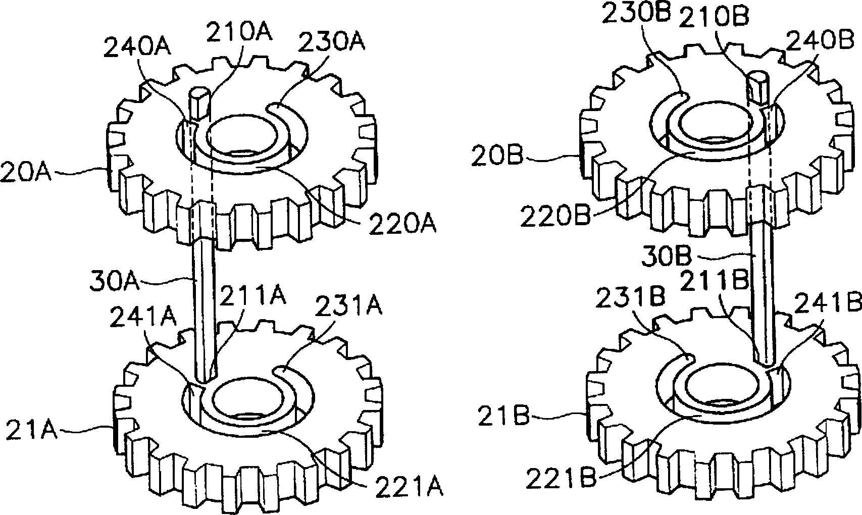
Disclosed is a cutting blade bending apparatus. The apparatus comprises a nozzle section for feeding a cutting blade into a bending area through a guide opening which is defined therein in a lengthwise direction of the cutting blade; a first bending member for bending the cutting blade fed into the bending area, in one direction; a second bending member for bending the cutting blade fed into the bending area, in the other direction; a first rotating body for firmly supporting the first bending member and guiding rotation of the second bending member; a second rotating body for firmly supporting the second bending member and guiding rotation of the first bending member, the second rotating body being rotated independent of the first rotating body; and a driving section for rotatably driving, at a time, one of the first and second rotating bodies.

Description

technical field [0001] The invention relates to a cutting blade bending device, and more specifically, the invention relates to a cutting blade bending device capable of precisely forming acute angles. Background technique [0002] Various cutting blade bending devices have been disclosed in this field. [0003] First refer to Figure 7a , which is a cross-sectional view of the cutting blade bending device described in International Patent Publication No. WO95 / 0026. In this cutting blade bending device, when the cutting blade 100 passes through the guide opening formed by the fixed mold 70, it moves forward under the rotation of the rollers 92, 93, and the cutting blade is mounted on the movable mold 71 which is rotatable around the fixed mold 70. function and bend. That is to say, when the movable mold 71 rotates, the end 711,711 of the movable mold will be folded to one side by the end 700,700 of the fixed mold 70. bend. However, such a conventional cutting blade bendi...

Claims


Application Information

Patent Timeline
IPC IPC(8): B21D53/64B21D5/16B21D5/04B21D5/00B21D37/20
CPCB21D37/205B21D5/00
Inventor 朴洪顺
Owner 朴 洪顺
Learn More