LED luminaire with optical sensor structure for optical feedback

A technology of light-emitting diodes and optical sensors, which is applied to optical elements, electroluminescent light sources, and devices with multiple detectors for changing the spectral characteristics of emitted light, etc. question

Inactive Publication Date: 2006-02-08
SIGNIFY HLDG BV
View PDF1 Cites 1 Cited by
  • Summary
  • Abstract
  • Description
  • Claims
  • Application Information

AI Technical Summary

Problems solved by technology

The light output of LEDs also varies inversely with temperature, but this variation is not uniform for each color
Also, in LED arrays, damage to individual chips can alter the light output

Method used


Image

  • LED luminaire with optical sensor structure for optical feedback
  • LED luminaire with optical sensor structure for optical feedback
  • LED luminaire with optical sensor structure for optical feedback

Examples


Embodiment Construction

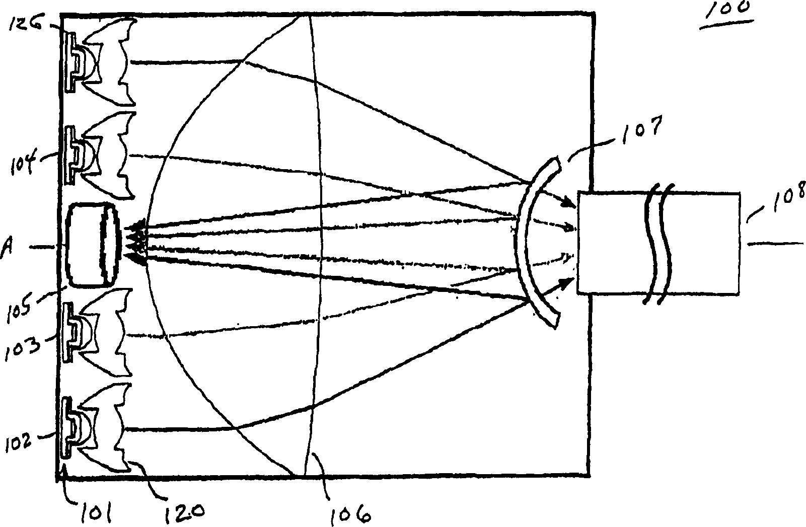
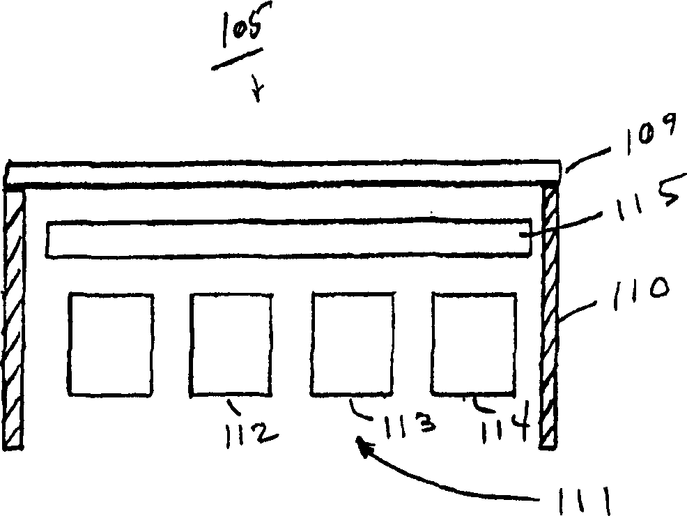
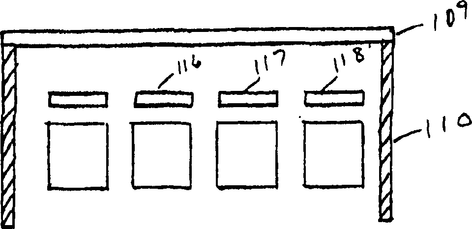
[0022] With reference to the accompanying drawings, figure 1 is a schematic cross-sectional view of one embodiment of the optical components of the RGB light emitting diode light source of the present invention, the light emitting diode array 101 includes individual light emitting diode assemblies (102, 103, 104), which are arranged in two concentric rings around the central axis A stand-alone LED components. Each LED assembly includes a sealed LED package 126 and a collimating lens 120 . Optical sensor assembly 105 is located on central axis A and includes diffuser 109, concentrator 110, and photodiode arrays 112, 113, 114 (see figure 2 and 3 ).

[0023] The main condenser lens 106 directs the light output from the LED array 101 to the target light guide 108 . A suitably shaped partial reflector 107 is provided in the region between the main condenser lens 106 and the target light guide 108 . The partial reflector 107 should have a total reflectivity of about 1%, which ...


PUM


Abstract

White light emitting LED luminaire incorporates an array of red, green and blue emitting LEDs and a feedback arrangement to maintain a desired color balance. The feedback arrangement includes photodiodes positioned and enabled to separately measure the light output of each RGB color component. In one embodiment, a single photodiode or array of photodiodes is positioned to intercept reflected light from a partially reflecting element placed in the path of the combined output of the LED array. Individual colors are measured sequentially by pulsing the LEDs and photodiodes or by the use of color filters. In an alternate embodiment, each LED has an associated photodiode, either incorporated into the LED package or in a separate package.

Description

technical field [0001] The present invention relates to a white light emitting light source having an array of red, green, and blue light emitting diodes (LEDs) and to a control system for adjusting the light output of individual components to maintain a desired color balance (chromaticity) , the invention particularly relates to such a light emitting diode light source with an optical sensor structure for light feedback. Background technique [0002] White-emitting light sources have arrays of red, green, and blue light-emitting diodes (LEDs) (also known as RGB (red, green, and blue) light-emitting diode light sources), due to high efficiency, low cost, and adjustable color of light output. For reasons such as high temperature, the light source that emits white light has attracted attention. [0003] An important issue to address is that the light output of the LEDs therein varies from chip to chip and over the lifetime of each chip. The light output of LEDs also varies i...

Claims


Application Information

Patent Timeline
Patent Type & Authority Patents(China)
IPC IPC(8): F21V23/04F21V9/10H05B33/08F21V5/04F21V8/00F21V9/08F21V9/40F21Y101/02G01J1/04G01J1/32G01J1/42G02B6/42H05B37/02H05B44/00
CPCG01J1/4228F21Y2113/005G01J1/32G02B6/0006G02B6/4204H05B33/0869G01J1/0488H05B33/0821G01J2001/4252F21Y2101/02F21V23/0457F21Y2115/10F21Y2113/13H05B45/40H05B45/22H05B45/00G09G3/14
Inventor T·M·马沙尔M·D·帕斯利F·J·P·舒尔曼斯
Owner SIGNIFY HLDG BV
Why Eureka
Try Eureka