Nail magazine for power nailer

A nail cartridge and nail driving technology, applied in the field of nail cartridges, can solve the problems of expensive, bulky nail driving machine, difficult to use, etc.

Inactive Publication Date: 2006-02-15
ARROW FASTENER CO INC
View PDF0 Cites 0 Cited by
  • Summary
  • Abstract
  • Description
  • Claims
  • Application Information

AI Technical Summary

Problems solved by technology

Typically these cartridges are adapted to hold a single size of nails, so their flexibility is limited
While some power nailers have magazin

Method used


Image

  • Nail magazine for power nailer
  • Nail magazine for power nailer
  • Nail magazine for power nailer

Examples


Embodiment Construction

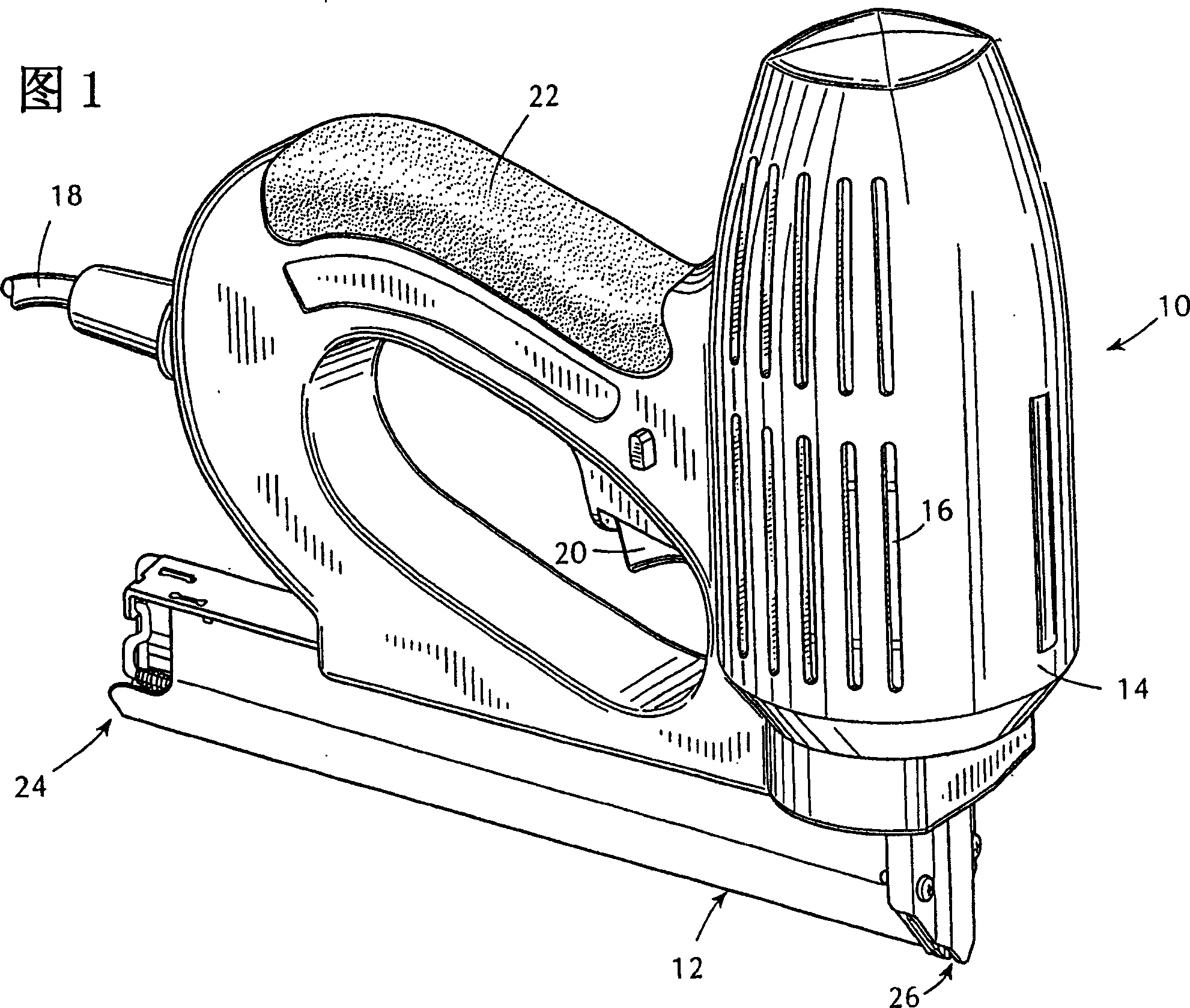
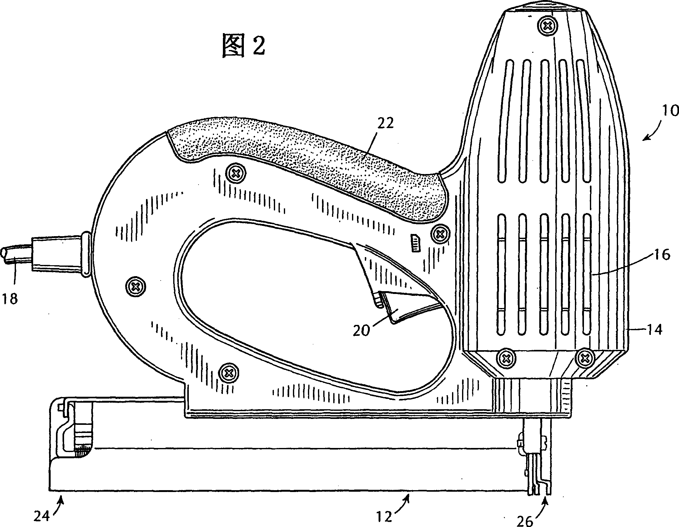
[0017] Referring now to FIG. 1, there is shown an electric nailer 10 incorporating a staple cartridge 12 constructed in accordance with the present invention. The nailer 10 has a housing 14 containing a conventionally constructed drive head 16 therein. Power is supplied to the head 16 from a power supply line 18 . A conventional trigger mechanism (trigger) 20 is provided on the handle 22 for operating the power head and driving the nails within the cartridge 12 . The power head 16 is provided with a solenoid arrangement or electric motor to reciprocate a hammer or so-called "machete" in known manner, acting on top of the nails in the magazine 12 to drive the nails into the workpiece.

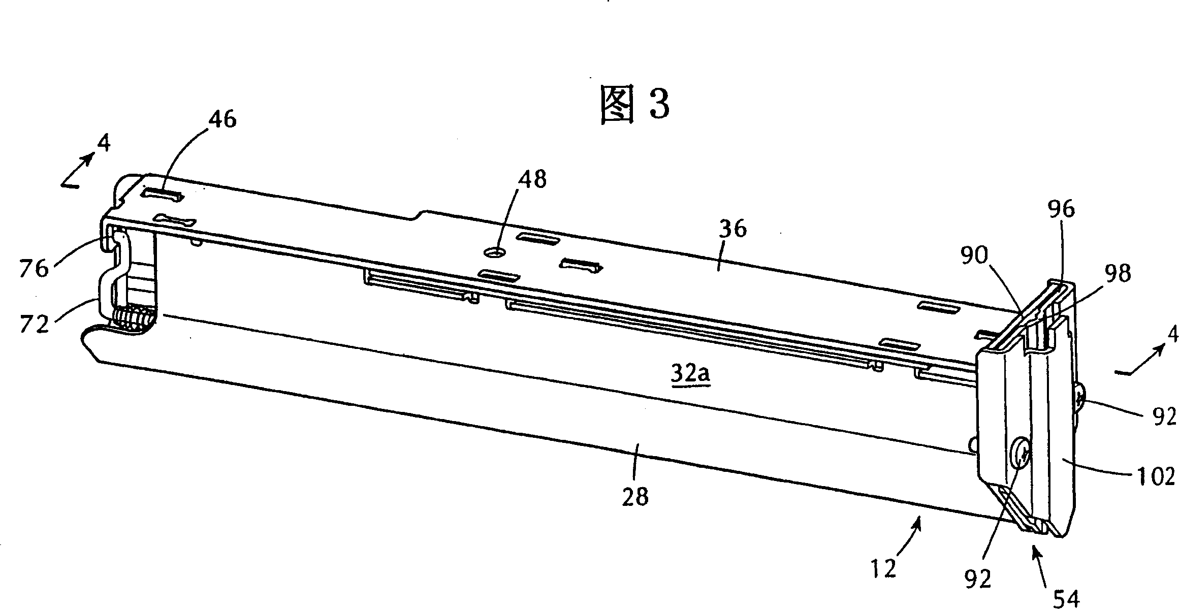
[0018] The staple cartridge 12 has a staple loading rear end and a front end 26 located below the power head 16 . As can be seen from Figure 7, the staple cartridge 12 has a housing 28, the housing as Figure 5 and 6 There is shown a generally V-shaped face 30 and two parallel side walls 32a...


PUM


Abstract

A nail magazine (12) for a power nailer (10) is disclosed which includes an elongated housing (34) formed from a pair of parallel side walls (44) which have a plurality of opposed elongated channels (48a, 48b, 48c) formed therein cooperating to define a plurality of guide tracks which receive the heads (50) of a strip of nails (52) fitting between the side walls (44). The side walls (44) have a discharge end (54) from which nails (52) in the strip are discharged. The nails (52) are biased towards the discharge end (54) of the strip by a spring pusher arrangement (56) including a flat plate (58) received between the side walls (44).

Description

technical field [0001] The invention relates to a nail magazine for a power nailing machine, in particular to a nail magazine suitable for receiving nails of various lengths. Background technique [0002] Power nailers, both electric and pneumatic, have been known for many years. These nailers typically include a nail magazine adapted to hold a strip of nails which may be driven one at a time by a reciprocating machete or hammer as the strip is driven through the drive head. Typically these cartridges are adapted to hold a single size of nails, so their flexibility is limited. While some power nailers have magazines that can hold nails of different sizes, these nailers are generally cumbersome and expensive to manufacture, and they are sometimes difficult to use. Contents of the invention [0003] It is an object of the present invention to provide a nail cartridge for a power nailer which can be used to receive nails of several different sizes. [0004] Another object ...

Claims


Application Information

Patent Timeline
IPC IPC(8): B25C1/04B25C1/00B25C5/16
CPCB25C5/1658B25C1/005
Inventor 鲁多夫·温格特
Owner ARROW FASTENER CO INC
Why Eureka
Try Eureka