Small size antenna

A small antenna and helical technology, applied in resonant antenna, antenna support/installation device, radiating element structure and other directions, can solve the problem of increasing the installation area of ​​the antenna

Inactive Publication Date: 2006-04-12
FURUKAWA ELECTRIC CO LTD +1
View PDF2 Cites 0 Cited by
  • Summary
  • Abstract
  • Description
  • Claims
  • Application Information

AI Technical Summary

Problems solved by technology

Furthermore, since the existing antenna must be installed away from the edge of the ground plate to some extent, there is also a problem of increasing the area required for installing the antenna.

Method used


Image

  • Small size antenna
  • Small size antenna
  • Small size antenna

Examples


Embodiment Construction

[0028] Hereinafter, we will describe the embodiments of the present invention in detail with reference to the drawings.

[0029] [First Embodiment]

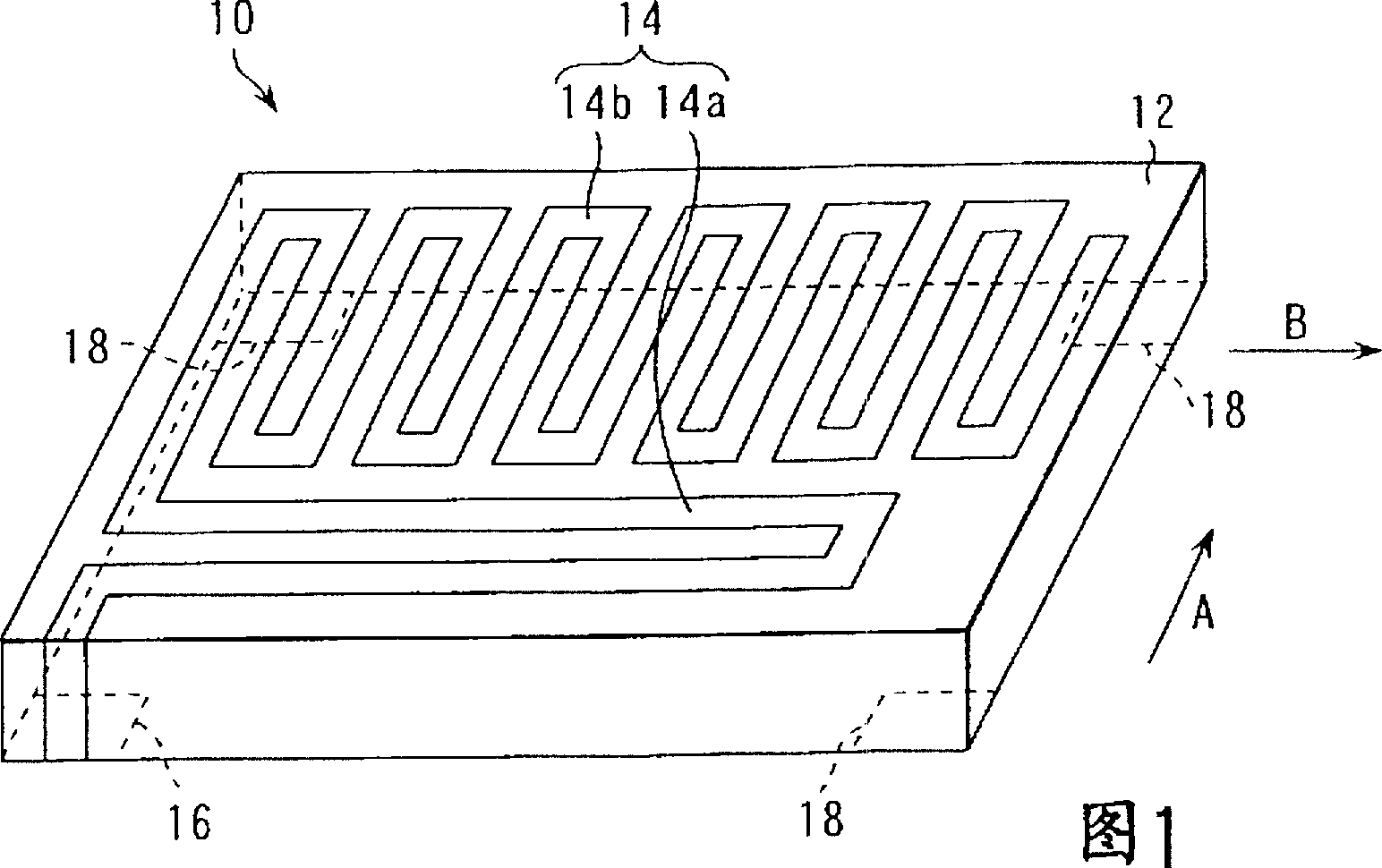
[0030] Fig. 1 is a perspective view of a small antenna according to a first embodiment of the present invention. The small antenna 10 related to the first embodiment has a flat dielectric substrate 12, an antenna conductor 14 provided on one surface of the dielectric substrate 12, and an antenna conductor 14 provided on one corner portion of the other surface of the dielectric substrate 12. Feed terminal part 16. This antenna forms an electrical length of substantially 1 / 4 wavelength of a frequency band in which signals are transmitted and received.

[0031] The antenna conductor 14 has a first meandering portion 14a and a second meandering portion 14b. The first meandering portion 14a is formed to meander in a certain direction (the direction of arrow A in FIG. 1 , that is, the direction of the short side of the substrate) fr...


PUM


Abstract

A small antenna characterized by comprising a first meander part formed in such a manner that a meander conductor travels to a first direction and having a first end and a second end, and a second meander part formed in such a manner that a meander conductor travels to a second direction different from the first direction and having a first end connected with the second end of the first meander part and a second end.

Description

[0001] Cross References to Related Patent Applications [0002] This patent application builds on and has priority over the previous Japanese Patent Applications No. 2000-311533 filed on October 12, 2000 and Japanese Patent Application No. 2000-311534 filed on October 12, 2000 rights, the entire contents of these patent applications are hereby incorporated by reference. technical field [0003] The present invention relates to a small-sized antenna for a portable phone, a portable information terminal, a terminal device of a wireless LAN (Local Area Network), and the like. Background technique [0004] Conventionally, as small-sized antennas for cellular phones, there are antennas in which an antenna conductor is formed in a meandering shape on the surface of a dielectric substrate (refer to Japanese patent publication No. An antenna in which an antenna conductor is formed on the ground (refer to Japanese Patent Publication No. 10-98322 published in 2010) is well known. ...

Claims


Application Information

Patent Timeline
IPC IPC(8): H01Q1/38H01Q1/24H01Q9/42H01Q1/36H01Q9/04
CPCH01Q1/38H01Q1/36H01Q9/0407H01Q9/42H01Q1/24
Inventor 和城贤典矶洋一今川敏幸大关实
Owner FURUKAWA ELECTRIC CO LTD
Why Eureka
Try Eureka