
Device on spinning machine for compressing fibre bundle

A spinning frame and fiber technology, which is applied to spinning machines, continuous winding spinning machines, textiles and papermaking, etc., can solve the problems of suction channel wear and other problems, and achieve the effect of less fluff

Inactive Publication Date: 2006-05-03
MASCHINENFABRIK RIETER AG
View PDF1 Cites 0 Cited by
  • Summary
  • Abstract
  • Description
  • Claims
  • Application Information

AI Technical Summary

Problems solved by technology

[0004] In the known drive there is the disadvantage that the gripping rollers used to make the friction drive possible must be applied to the conveyor belt with a minimum pressure which needs to be higher than the pressure used for the twist stop function
In combination with the friction of the conveyor belt and the sliding surface, this leads to increased wear of the suction channel at the area of ​​the output jaw line

Method used


Image

  • Device on spinning machine for compressing fibre bundle
  • Device on spinning machine for compressing fibre bundle
  • Device on spinning machine for compressing fibre bundle

Examples


Embodiment Construction

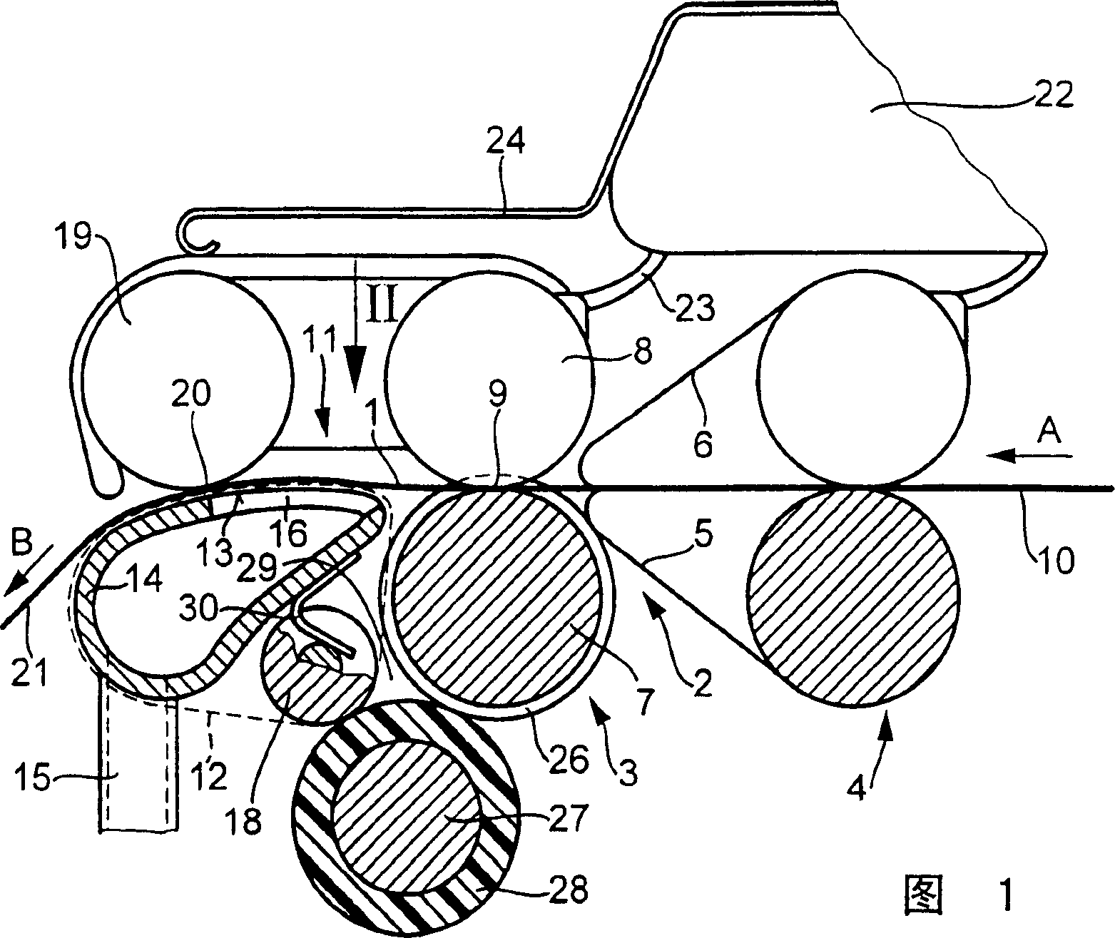
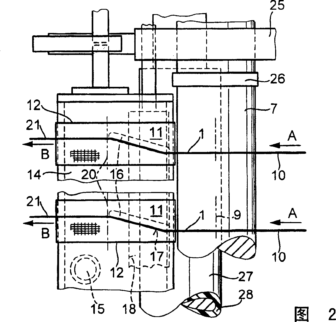
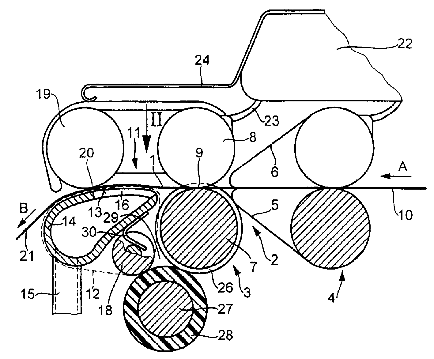
[0013] In a spinning frame, in particular a ring spinning frame, only the end region of a drafting device 2 is shown in relation to a device for compacting a fiber strand 1 . The drafting device 2 itself only shows a pair of output drafting rollers 3 and a pair of aprons 4 upstream of the pair of output drafting rollers, which pair of aprons has a lower apron 5 and an upper apron 6 . The output drafting roller pair 3 itself comprises a driven bottom roller 7 and a drafting top roller 8 which define an output nip line 9 . On this output nip line 9 the front drafting zone of the drafting device 2 ends.

[0014] In the drafting device 2 a fiber sliver or a roving 10 is drawn in a known manner in the conveying direction A to the desired fineness. After the junction of the output drafting roller pair 3 there is a compacting zone 11 in which the drawn but still untwisted fiber strand 1 is bundled or compacted.

[0015] An air-permeable conveyor belt 12 belonging to the compaction ...


PUM


Abstract

A compacting zone for compacting a drawn, untwisted fiber strand is located after the drafting unit of a spinning frame. The compaction zone includes an air-permeable conveyor belt (12) which transports the fiber strands through the compaction zone. Here, the conveyor belt is guided on the sliding surface (13) of a suction channel (14) and tensioned by a deflection roller (18). In the sliding surface (13) there is a suction slot extending approximately in the transport direction of the fiber strand. The end of the compaction zone is limited by a gripping roller (19) which compresses the fiber strand and the conveyor belt against the sliding surface. The deflection roller is arranged in the area of ​​the bottom roller (7) of the driven output drafting roller pair (8, 7) and forms a wedge-shaped gap with the bottom roller. In this wedge-shaped gap (29), an intermediate roller rests not only on the bottom roller but also on the diverting roller, thereby driving the conveyor belt.

Description

technical field [0001] The invention relates to a device for compacting a fiber sliver on a spinning frame, which device has a front drafting zone delimiting a drafting device, comprising a driven bottom roller and a drafting top roller The output drafting roller pair; has a compacting zone located after the previous drafting zone; has an air-permeable conveyor belt for transporting fiber strands through this compacting zone; has a The conveyor belt is guided on a suction channel on a sliding surface; there is a suction slot in the sliding surface; there is a gripping roller delimiting the end of the compaction zone, which presses against the sliding surface; there is a a diverting roller tensioning the conveyor belt; and a drive unit for the conveyor belt cooperating with the bottom roller. [0002] If the drawn fiber strands are directly connected to the pair of output rollers of the drafting device for twisting, a so-called spinning triangle will appear on the nip line of ...

Claims


Application Information

Patent Timeline
Patent Type & Authority Patents(China)
IPC IPC(8): D01H5/72D01H5/86D01H1/22D01H5/70
CPCD01H5/72D01H1/22D01H5/86
Inventor G·谢夫勒G・谢夫勒
Owner MASCHINENFABRIK RIETER AG
Learn More