Parallel gripper

A technology of parallel grippers and grippers, applied in the direction of collets, chucks, manipulators, etc., can solve problems such as deformation and shell distortion, and achieve the effect of a compact overall structure

Inactive Publication Date: 2006-06-28
顺科两合公司夹具和抓取工具厂
View PDF0 Cites 2 Cited by
  • Summary
  • Abstract
  • Description
  • Claims
  • Application Information

AI Technical Summary

Problems solved by technology

However, if the wall thickness of the housing is reduced, in particular when introducing and transmitting the clamping force, undesired distortions and deformations of the housing can occur, which are undesirable in view of the precision to be achieved

Method used


Image

  • Parallel gripper
  • Parallel gripper
  • Parallel gripper

Examples


Embodiment Construction

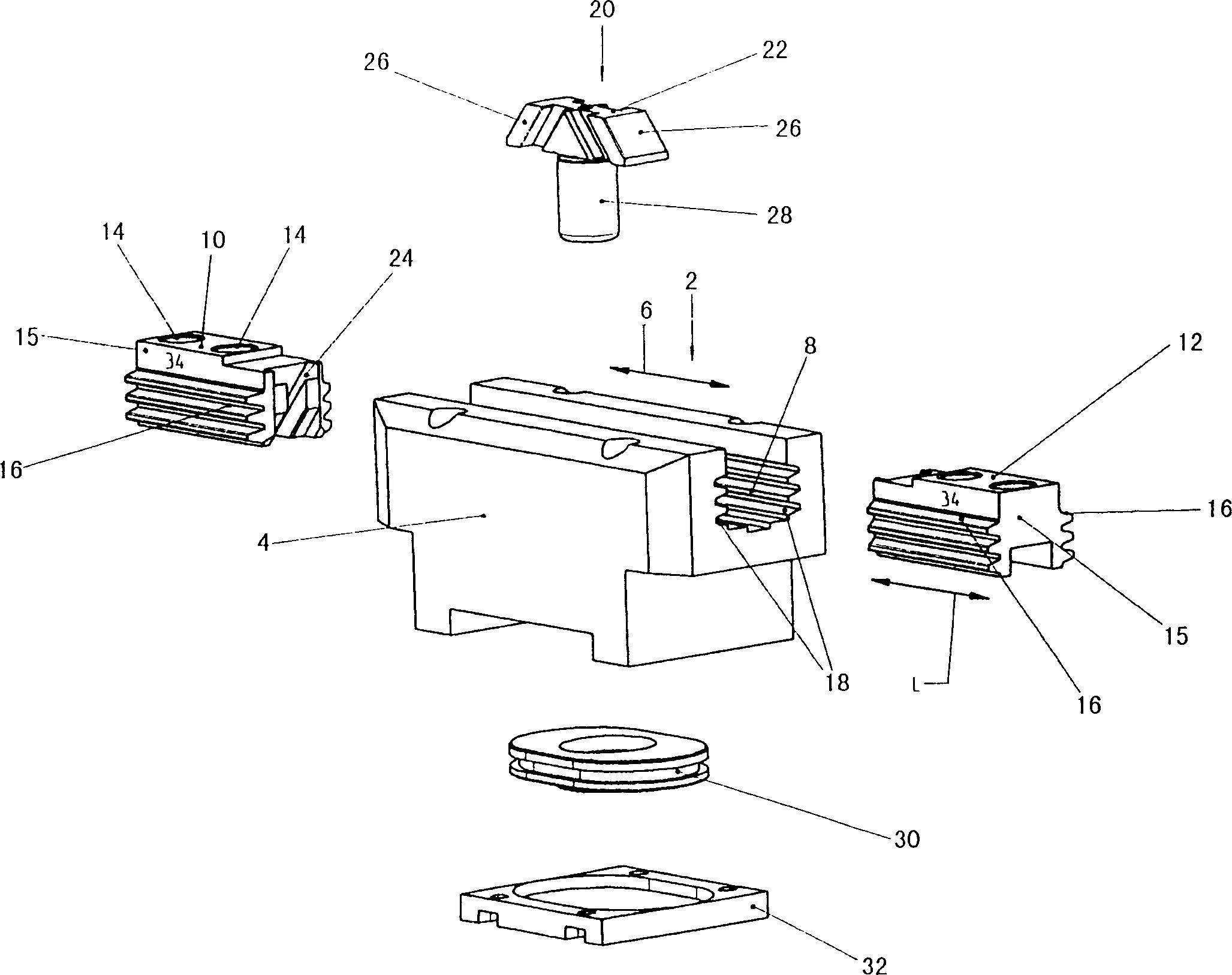
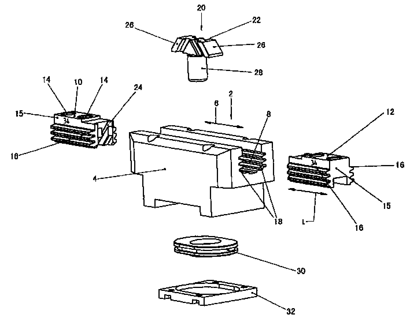
[0022] figure 1 A parallel gripper, generally designated by reference numeral 2, is shown. The gripper comprises a gripper housing 4 with gripper guide recesses 8 extending in the longitudinal direction 6 for the basic grippers 10 and 12, which are shown outside the housing and can be It is inserted in the longitudinal direction 6 into the guide recess 8 of the clamping block and can be moved therein. On one surface of the basic clamping blocks 10, 12 are provided mounting holes 14 for detachably attaching jaw elements, which will not be further described here.

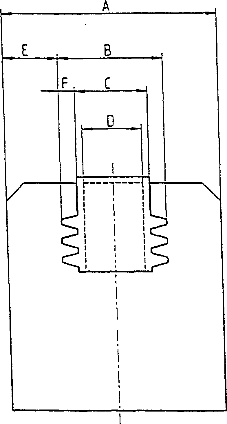
[0023] The basic clamping blocks 10 , 12 each have guide strips 16 extending in the longitudinal direction 6 and thus in the direction of movement on both sides, which are wedge-shaped or trapezoidal in shape with flattened ends. On both sides of each basic clamping block 10 , 12 three guide strips 16 arranged one above the other protruding from its base body 15 and extending over the entire length L of the basic cl...


PUM


Abstract

The invention relates to a parallel gripper comprising a housing (4) and two adjustable gripper base jaws (10, 12) which are guided in the housing (4) in a jaw guiding recess (8) in a displaceable manner. The base jaws (10, 12) can be moved towards or away from one another by means of a wedge hook gearing (20) that can be adjusted by means of a piston (30) that is guided in said housing. The aim of the invention is to provide a compact parallel gripper for transmitting and receiving great gripper forces or overturning moments. According to the invention, the parallel gripper is configured in such a way that the piston (30) is provided with an oval or essentially rectangular form having rounded edges and that the base jaws (10, 12) are provided with at least two guiding webs (16) on both sides respectively. Said webs are rectangular, wedge-shaped or trapezoidal in the cross-section thereof and extend in the direction of displacement (6). The jaw guiding recess (8) is provided with guiding grooves (18) which are configured complementary thereto. The ratio of the wall thickness (E) of the housing (4) measured between the base of the guiding grooves (18) and the outside of the housing in relation to the width (A) of the housing measured vertically in relation to the direction of displacement(6) of the base jaws (10, 12) amounts to at least 0.2. The ratio of the width of inclined traction of the wedge hook gearing (D) (20) in relation to the outside width (B) of the base jaws (10, 12) amounts to at least 0.4.

Description

technical field [0001] The invention relates to a parallel gripper with a housing and two movable basic gripper pieces of the gripper, which are guided displaceably in a gripper guide recess in the housing, wherein , the basic clamping pieces can be moved toward each other or apart by a wedge-shaped hook drive, which can be adjusted by a piston guided in the housing. Background technique [0002] Such parallel grippers are already known. In a known embodiment, caps forming the jaws can be mounted on two basic clamping blocks, which are generally T-shaped in cross-section and in the direction of movement, wherein the T The shaped cross leg is displaceably guided away from the workpiece in a correspondingly formed clamping block guide recess in the housing. There are also structures using rolling elements. In order to be able to generate high clamping forces and to be able to absorb the tilting moments that occur here, a correspondingly large guide width must be achieved wh...

Claims


Application Information

Patent Timeline
Patent Type & Authority Patents(China)
IPC IPC(8): B25J15/02F15B15/14B25J15/08B23B31/177
CPCB23B31/16237Y10T279/1973B23B31/16254B25J15/028B25J15/02
Inventor 格哈德·米希勒拉尔夫·温克勒
Owner 顺科两合公司夹具和抓取工具厂
Why Eureka
Try Eureka