
Flatbed knitting machine

A knitting machine and horizontal technology, applied in weft knitting, flat knitting machines with individual moving needles, knitting, etc., can solve the problem of changing work requiring a lot of labor

Inactive Publication Date: 2006-07-12
SHIMA SEIKI MFG LTD
View PDF1 Cites 0 Cited by
  • Summary
  • Abstract
  • Description
  • Claims
  • Application Information

AI Technical Summary

Problems solved by technology

Depending on the hook size (L, M, S) on the needle bed, changing the position of the positioning pin relative to the positioning hole pierced in the base of the body requires manual operation. Although a special drive device like the above is not required, but For the staff, the change work requires a lot of labor

Method used


Image

  • Flatbed knitting machine
  • Flatbed knitting machine
  • Flatbed knitting machine

Examples


Embodiment 1

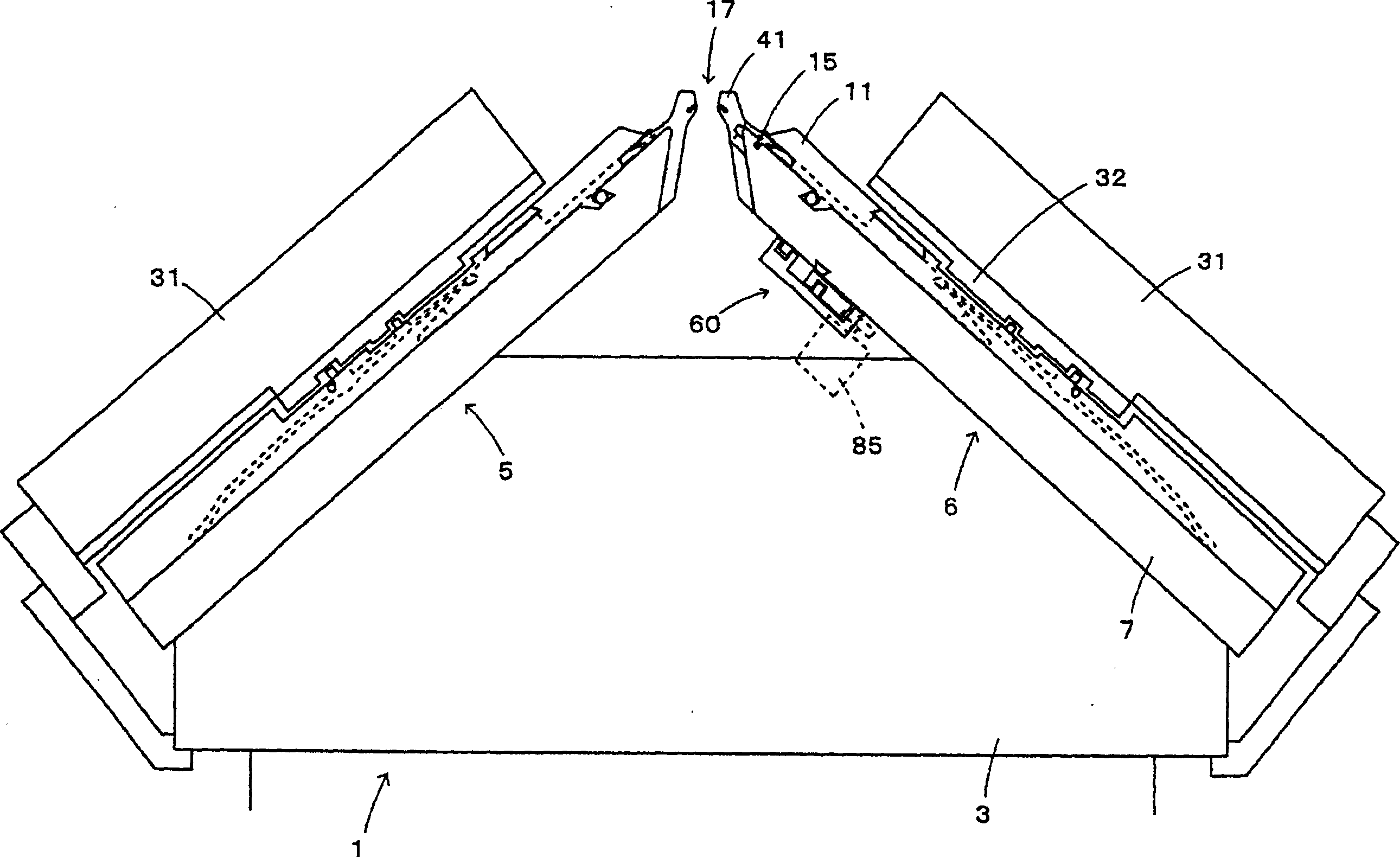
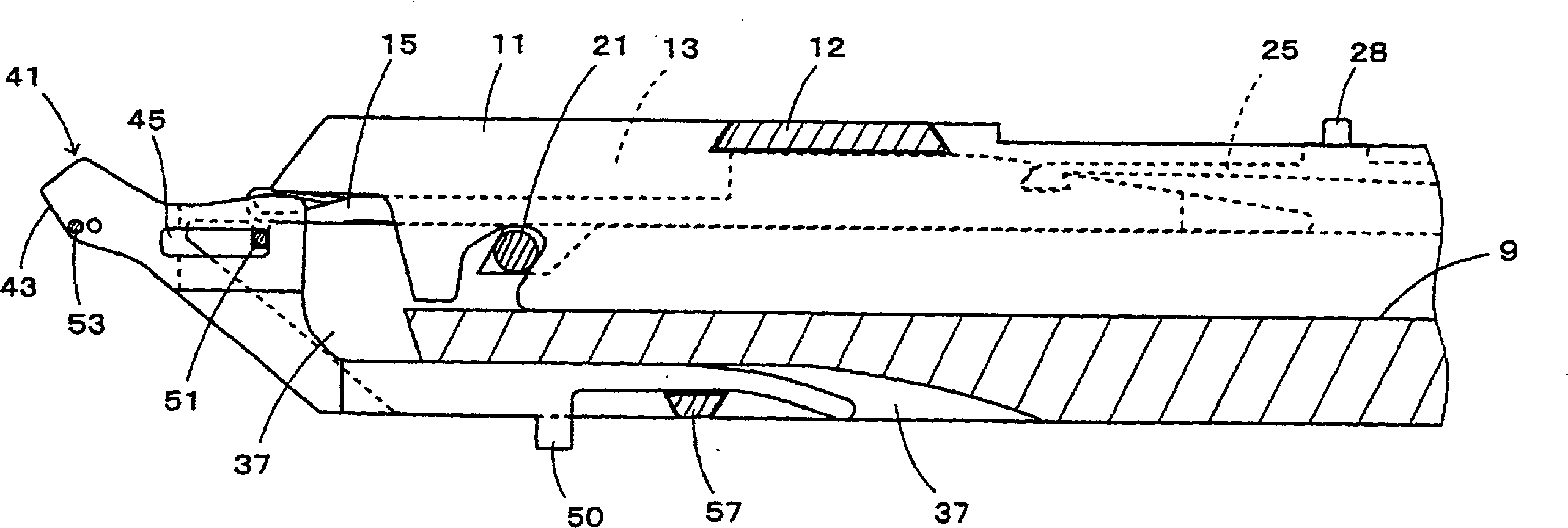
[0036] In the transverse knitting machine 1 of this embodiment, the front and rear needle beds formed by arranging a plurality of needles and sinkers in parallel are oppositely arranged in an inverted V shape. figure 1 It is a side view schematically showing the needle bed portion of the horizontal knitting machine. figure 2 is a cross-sectional view showing the rear needle bed (the operating device described later is omitted), image 3 yes figure 2 Enlarged view of the frontmost portion of the needle bed shown. Fig. 4 is a diagram showing main parts constituting the needle bed. In this specification, the movement of the tooth gap between the front and rear needle beds is expressed as entering, and the opposite movement is expressed as backward. In addition, when describing each part of the horizontal knitting machine, the part facing the crest is shown as the front, and the opposite part is shown as the back.

[0037]The front needle bed 5 and the rear needle bed 6 are ...

Embodiment 2

[0054] The needle bed of the horizontal knitting machine in the above-mentioned embodiment has a structure in which the sinkers, through which the piano wires forming the tip of the needle bed are inserted, are supported at the front end of the needle bed freely. Needle bed 101 in, from Figure 9 It can be seen from the shown sectional view that the needle bed base plate 103 is formed separately from the body portion 105 and the front end portion 107 . 10a and 10b show a state in which the main body portion 105 and the front end portion 107 constituting the needle bed base plate 103 are separated.

[0055] On the front end portion of the substrate body portion 105 of the needle bed 101, a support portion 111 is formed, and the support portion 111 is embedded in a recessed portion 113 formed on the rear end surface of the substrate front end portion 107 to support the substrate front end portion 107 on the substrate body. Section 105 on. Grooves 117 and 118 for inserting the ...


PUM


Abstract

A flat knitting machine (1) comprising a number of needles (15) arranged in needle grooves (13) formed on needle beds (5, 6) in such a manner as to be freely advanced or retracted; sinkers (41, 123), arranged between the needles (15, 15), to work to form loops; and at least a pair of front and back needle beds having a front edge portion (53, 121) and arranged to confront each other across a needle bed gap, wherein the sinker (41, 123) and the front edge portion (53, 121) of the needle bed are both supported on the needle bed in such a manner as to be movable in an advancing and retracting direction of the needle and also control means (60, 151) is provided for controlling an advanced or retracted motion of both of the sinker (41, 123) and the front edge portion (53, 121) of the needle bed, to adjust a dimension of the needle bed gap between the front and back needle beds (5, 6).

Description

technical field [0001] The present invention relates to a horizontal knitting machine with needle beds whose width of the gap between front and rear needle beds can be adjusted. Background technique [0002] In the horizontal knitting machine, at least a pair of front and rear needle beds are arranged so that the respective heads are close to each other with a gap between the needle beds. Many needles and sinkers are arranged side by side on each needle bed. The size of the gap formed between the tip of the needle bed facing each other and the sinker (hereinafter referred to as the tooth gap) is determined by the gauge and the hook size of the knitting machine. In some horizontal knitting machines, the gap size is adjustable. The tip portion is formed either by a piano wire or by the needle bed base itself. For example, a plurality of positioning holes for inserting positioning pins for adjusting the size of the needle bed are perforated at both ends of the needle bed. Ac...

Claims


Application Information

Patent Timeline
Patent Type & Authority Patents(China)
IPC IPC(8): D04B7/04D04B15/10D04B15/36D04B15/06
CPCD04B15/10D04B7/04D04B15/36D04B15/06D04B15/362
Inventor 森田敏明生驹宪司
Owner SHIMA SEIKI MFG LTD
Learn More