Permanent magnet synchronous linear motor
A permanent magnet and linear motor technology, applied in electrical components, electromechanical devices, propulsion systems, etc., can solve problems such as pitch staggering, low effect of reducing high-order components, and reducing the effect of cogging effect
- Summary
- Abstract
- Description
- Claims
- Application Information
AI Technical Summary
Problems solved by technology
Method used
Image
Examples
Embodiment 1
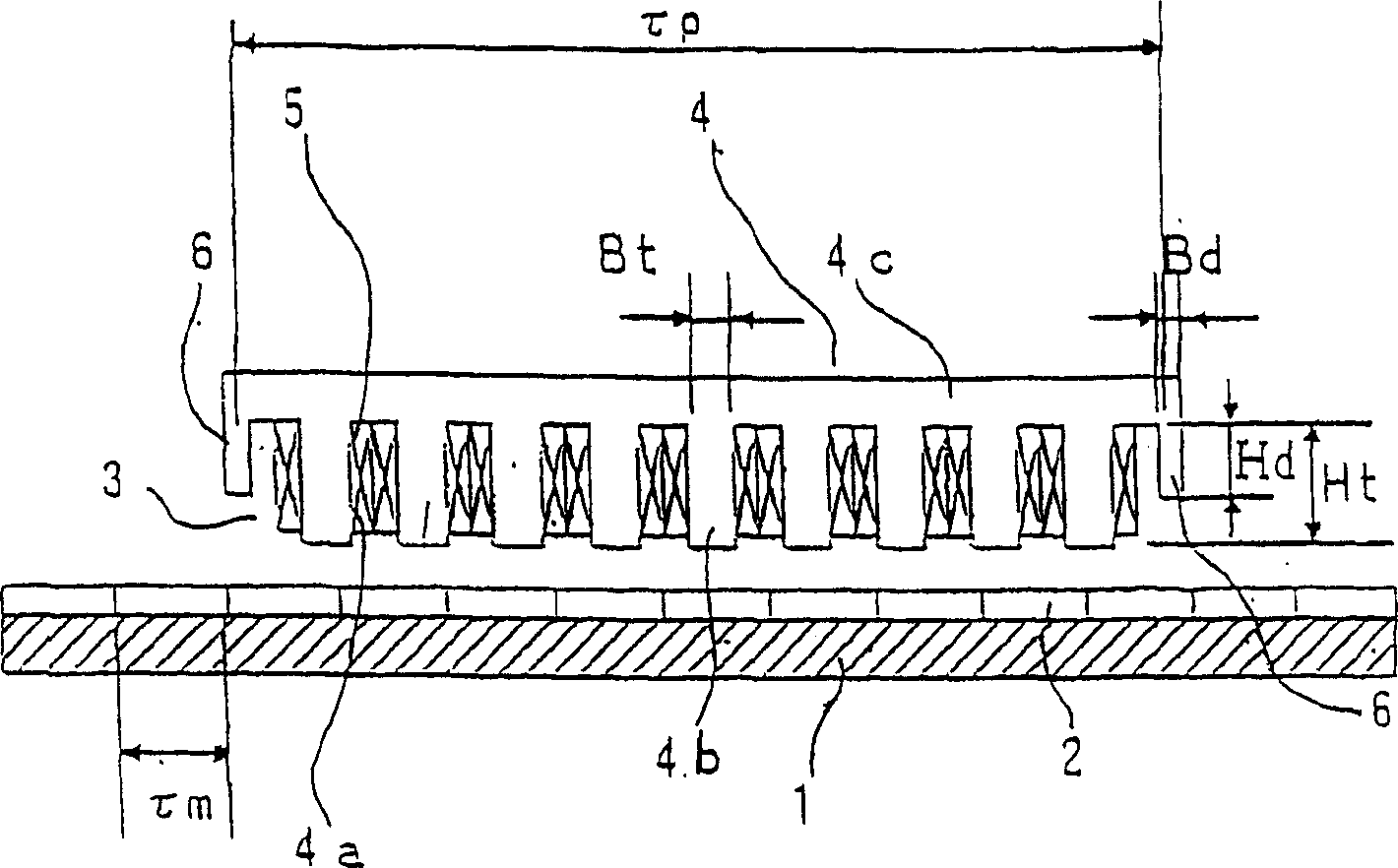
[0030] figure 1 It shows the permanent magnet type synchronous linear motor of the embodiment of the present invention. In order to illustrate the relationship between the main gear and the auxiliary gear of the embodiment 1-3, it is a side cross-sectional view of the common linear motor.
[0031] If the present invention and conventional components are the same, the same reference numerals will be used to omit the description, and only the differences will be described. Furthermore, this linear motor is an example showing the same 8 magnetic poles as in the prior art, and the gaps of 9 slots are opposed to each other.
[0032] figure 1 Among them, 3 is the armature, 4 is the armature core, 4a is the slot, 4b is the main tooth, 4c is the yoke, 5 is the armature coil, and 6 is the auxiliary tooth.
[0033]In this embodiment, the linear motor includes: a stator composed of permanent magnets 2 to be field poles, and a stator with slots 4a and main teeth 4b, and with auxiliary tee...
Embodiment 2
[0050] Next, use figure 1 To illustrate the second embodiment.
[0051] That is, the distance τ between the centers of the auxiliary teeth 6 P And field pole pitch τ m The relationship is made into τ P ≠(2n-1)×τ m Under the condition of / 2 (n is a positive integer), assume that the length of the auxiliary tooth 6 in the orthogonal direction along the permanent magnet 2 is Hd, and the main tooth 4b is in the orthogonal direction along the permanent magnet 2 When the length of is Ht, the length of the auxiliary tooth 6 is set to be in the range of 0≤Hd≤Ht.
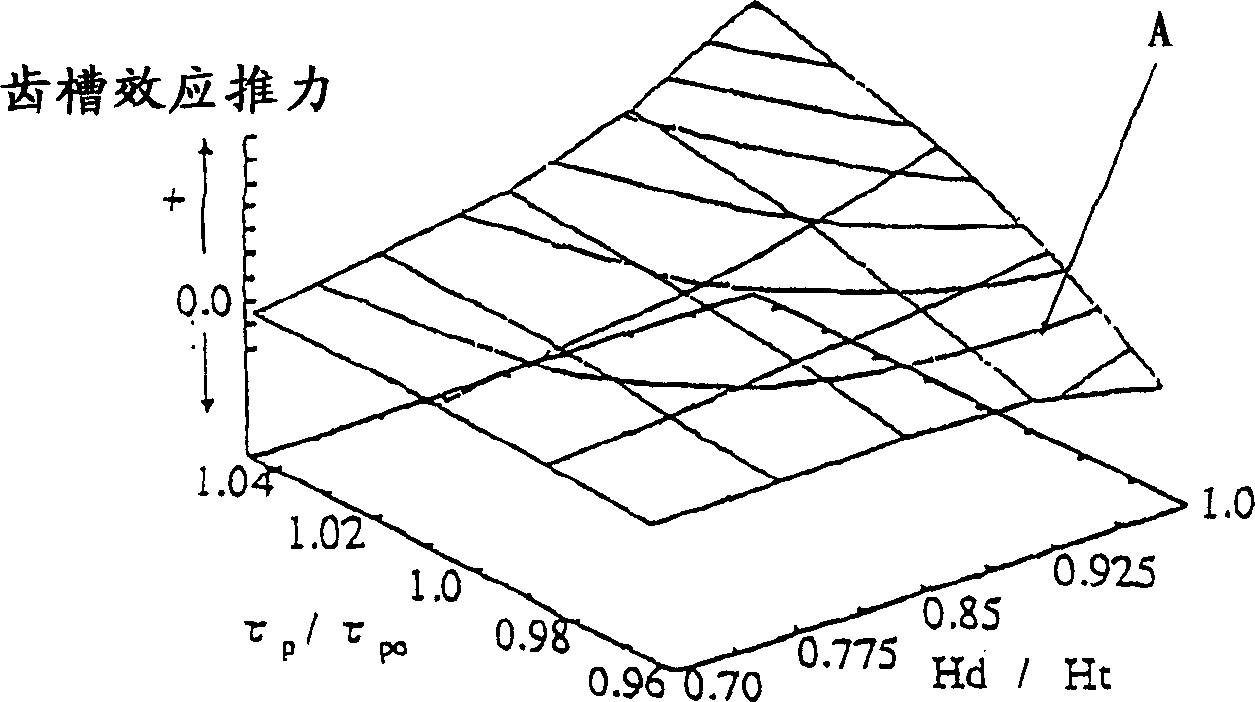
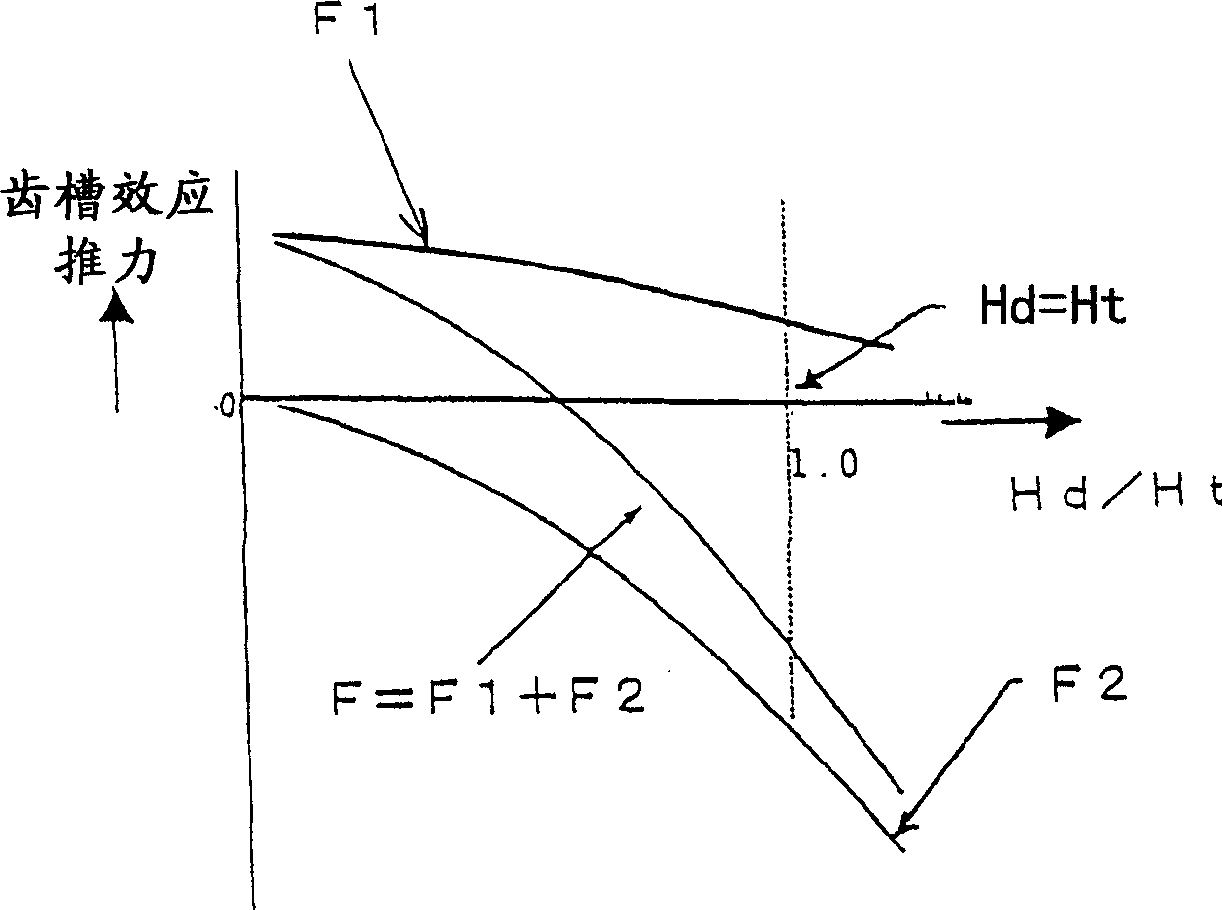
[0052] In the above configuration, the ratio Hd / Ht between the length Hd of the auxiliary tooth 6 and the length Ht of the main tooth 4b is set to be 0.50≦Hd / Ht≦1.
[0053] In the second embodiment, when the relationship between the length Ht of the main tooth 4b and the length Hd of the auxiliary tooth 6 is set as described above, as in the first embodiment, the cogging force can be reduced to substantially zero, and high-perf...
Embodiment 3
[0055] Next, use figure 1 To illustrate the third embodiment.
[0056] As explained in the prior art, the cogging waveform of a linear motor contains high-order components other than the primary component and higher than the secondary component for the magnetic pole pitch. The smaller the frequency, the larger the amplitude. For this reason, in order to reduce the cogging effect, it is mainly necessary to reduce the primary and secondary components.
[0057] Next, the effect of reducing the primary component or the secondary component by the auxiliary teeth 6 will be described. First, the relationship between the distance between the centers of the auxiliary teeth 6 and the cogging effect will be explained.
[0058] To reduce the primary component, as shown in Japanese Patent Publication No. 7-053427, the distance between the centers of the auxiliary teeth 6 is made τ P =(2n-1)×τ m / 2 is fine.
[0059] The distance between the centers of the auxiliary teeth 6 to cancel the second...
PUM
 Abstract
Description
Claims
Application Information
 - R&D Engineer
- R&D Manager
- IP Professional
- Industry Leading Data Capabilities
- Powerful AI technology
- Patent DNA Extraction
Browse by: Latest US Patents, China's latest patents, Technical Efficacy Thesaurus, Application Domain, Technology Topic.
© 2024 PatSnap. All rights reserved.Legal|Privacy policy|Modern Slavery Act Transparency Statement|Sitemap


